
This is a basic Guide to help with installation. Install was done on an 82 rabbit and 83 GTI. While there are some differences between make/model years and engines, the install will be generally the same across the board
CIS-E and CIS-E Motronic in MK2 Golf/Jetta/Scirocco are very similar, but harness routing is a little different. Follow notes below
The harness can be routed any way you would like for custom apps or even just cleaning up the bay with a tucked look. All sensor wiring is 7ft long, and can be easily removed from the split loom to reroute. Do not cut and splice the harness!!!!!
*Disclaimer*
*Please note You are going to be touching a fuel system and fuel which is flammable. Please take all the necessary safety precautions required and have a fire extinguisher on hand. BillT Industries assumes no liabilities or responsibility for any damages that may occur during the installation and tuning of this kit. It is the sole responsibility of the end user or installer to make sure this kit is installed properly*
Software Download - Downloads (tunerstudio.com)
The lite free version of ms is very limited. I recommend purchasing/registering the Ultra software for full feature and logging access all in one program
-

Step 1
Disconnect and Remove battery
-

Step 2
Remove intake S tube and breather hose
-

Step 3
Remove vac hoses to make room for injector removal
-
Remove this short hose from the center tee fitting. It will be reused for the map sensor
-

Step 4
Remove injectors. Easier said then done in some cases. If the seals are very hard and the injector wont come out take a thin sharp pick and poke at the injector seal to break it apart
-

Step 5
Unbolt and remove the cold start injector
-

Step 6
Start disconnecting the wiring for the cis. The thermo time switch can be unplugged but do not remove yet.
Note : This is located on the drivers side of the cylinder head on CIS-E 16v models. On CIS-E Motornic 16v this sensor is not there, instead an allen block off plug is installed. Remove this plug to install the new ECT sensor
-

Step 7
Unbolt and remove the control pressure/warm up regulator. This is not on any CIS-E systems
-

Injectors, cold start injector and wur almost ready for removal
-

Step 8
Remove fuel filter feed line to the fuel distributor. Place rags under the filter to catch the fuel that will come out
-

Step 9
Unbolt the fuel return line from the fuel distributor. It is the bigger line on the double banjo fitting
-

Step 10
Unbolt the 3 flathead screws (or torx in some cases) and remove the fuel distributor
-

Step 11
Unbolt the frequency valve
-

Complete fuel distributor and injectors removed
-

Step 12
Remove the fuel return line. It is the black plastic hose. Note depending how full your fuel tank is fuel may start flowing out have a plug handy to block the line off
-

Fuel return line temporarily plugged
-

Step 13
Start removing the old ignition system and wiring. The ignition control module/knock boxes will be removed
-

Unplug ignition distributor
-

Unbolt and remove ignition coil. Note: On early cars the coil wire has wing connection terminals on the connector, the later cars and aba coil in the kit have the stud style. I have added a new stud style connector end in the kit for early cars. Using silicone spray or another lube unscrew the connector from the coil wire and lube and screw on the new coil wire connector
-

In some vehicles the green signal wire to the ignition control module will be in the same connector as the red/black tach signal wire. The green wire will be removed
-

To remove the green wire use a thin pick or paperclip to push the locking tab.
-

Red/Black tach wire
-

Ignition control module and wiring removed
-

Step 14
Begin removal of the cis control module and wiring. On MK1 this is in the P/S foot well. The wiring will be pulled from the engine into the passenger compartment for removal
Note : On MK2 Jetta/Golf/Scirocco the modules/Knock Box/ECU are located in the drivers side rain tray
-

Cis control module and wiring removed
-

Step 15
Begin removal of the vacuum hoses to the ignition system
-

Remove and plug the hoses to the back of the throttle body
-

Step 16
Remove the plastic timing plug on top of the transmission to check TDC. You can use a 1” nut to help remove the plastic plug if stuck
-

1” nut to help removed plastic timing plug
-

-

Crank pulley at TDC. You must check the ignition distributor and flywheel as well
-

Ignition distributor at TDC. The center of the rotor will be inline will the groove on the distributor housing
-

Flywheel at TDC. Some Flywheels have a dot and V. In that case the Dot is tdc.
Some Flywheels have only a V. In that case the V is TDC
If uncertain at anytime where tdc is remove spark plug #1 and spin the motor over by hand to verify the piston is at the top of the its stroke. You can use a philips head screw driver as a reference, but take extreme care when doing this
-

Step 17
On vehicles with a vacuum advance ignition distributor, the distributor will be removed and replaced. CIS-E, CIS-E Motronic, Digifant 8v/16v will not be removed
-

New ignition distributor install at TDC
Note : Some new distributors will not have any tdc marks on them. In this case install the distributor so the rotor is pointing at cylinder 4 as in pic. Also verify your ignition wires are in the correct place on the distributor cap. Cylinder 1 wire will line up with the rotor position at tdc
-

Step 18
Remove Thermo Time Switch and install new ECT sensor.
Note : Loosen the radiator/overflow tank cap first to let any pressure out then retighten. This will help keep coolant from leaking out when the sensor is removed
-

Ect sensor installed in place of Thermo Time Switch
-

Step 19
Remove old CIS fuel injector Bungs and install new supplied bungs.
Note : I recommend putting a small amount of rtv sealant on the threads of the new bungs before install
-

Step 20
Install new ABA coil using supplied hardware. Note : The 8mm nut will act as a spacer to space the coil off the firewall. The flat side of the nut will go against the firewall
-

New ABA coil Installed.
On the new harness the Green/Yellow Tach wire will go to the Red/Black Tach wire removed from the original coil.
The Gray wire will go to the single black wire removed from the original coil
-

Step 21
Install new FPR onto fuel return line.
-

With the new FPR installed on the fuel return line, tweak the return line into place so the FPR bracket will bolt onto the supplied airbox mounting bracket
-

Step 22
Begin measuring the IAT sensor mounting hole location
-

-

Once measured out drill a 1/2” hole in the airbox. Do not drill the mounting hole yet
-

Install sensor temporarily to mark mounting hole drill location. Drill a 1/4” hole for mounting bolt and install sensor
-

IAT sensor installed. Reinstall airbox assembly
-

Step 23
Install cold start injector block off plate
-

Step 24
Install New fuel injectors, fuel rail, and mounting brackets. Lube injector o-rings with a little die electric grease or motor oil before installing
-

Step 25
Install new fuel return line hose from the 90* fitting on fuel rail to the FPR. It is important to make the loop in the return hose at the fuel rail fitting to keep the hos from kinking
-
-

Step 26
Install new fuel hose feed line from the straight fitting on the fuel rail to the supplied banjo fitting for the fuel filter
-

New feed line
-

New fuel feed line hose and banjo fitting installed on fuel filter
-
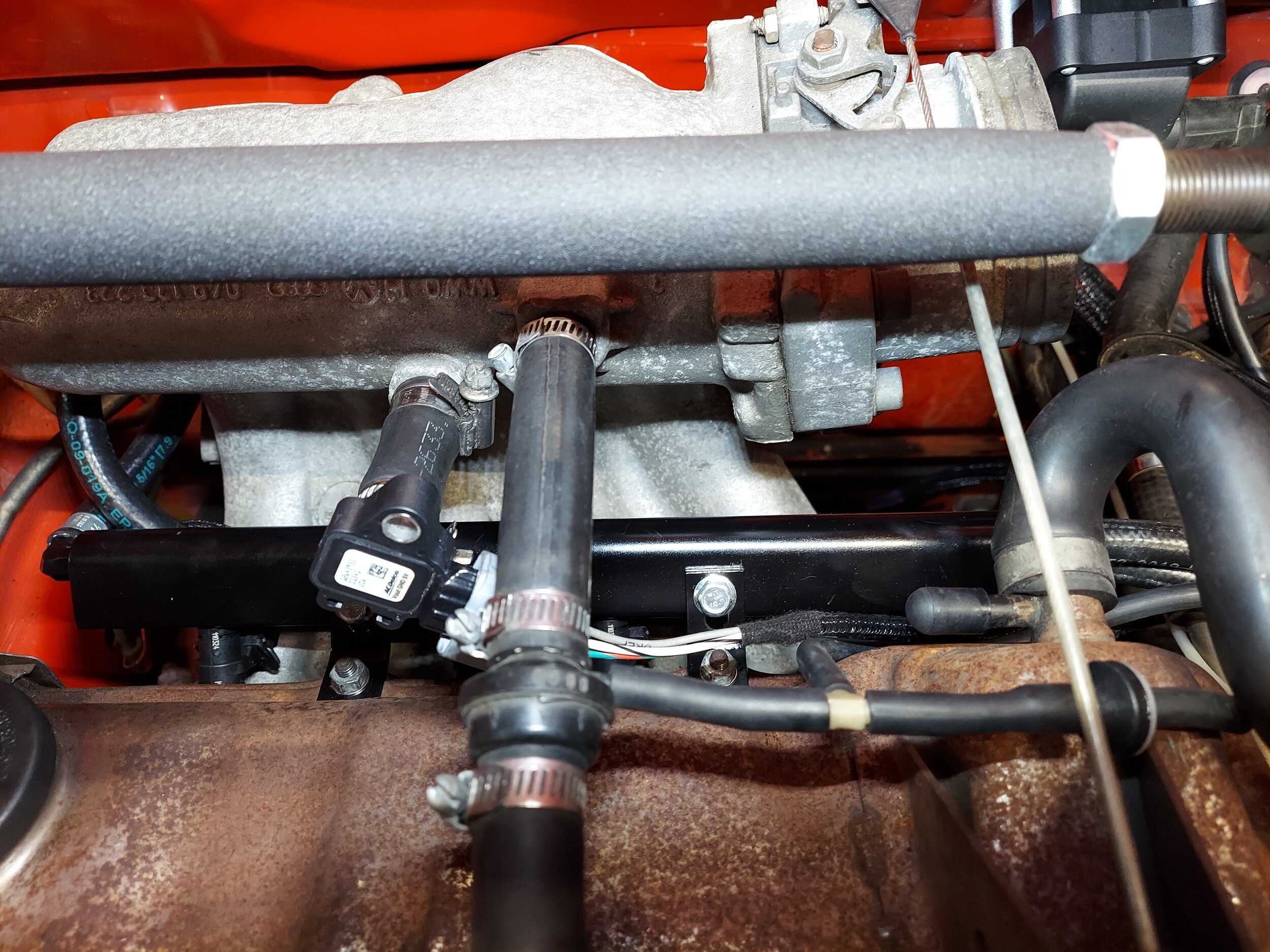
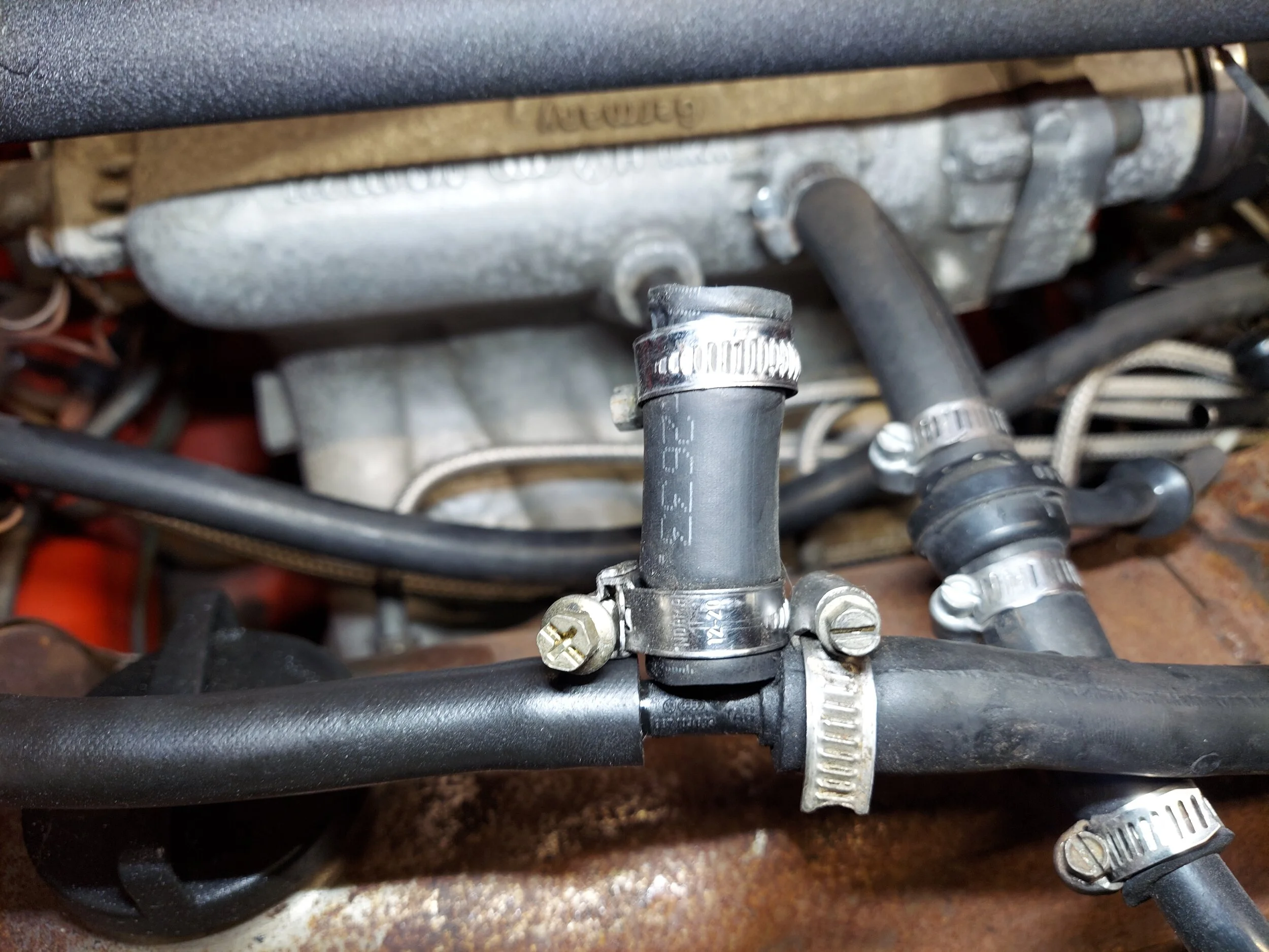
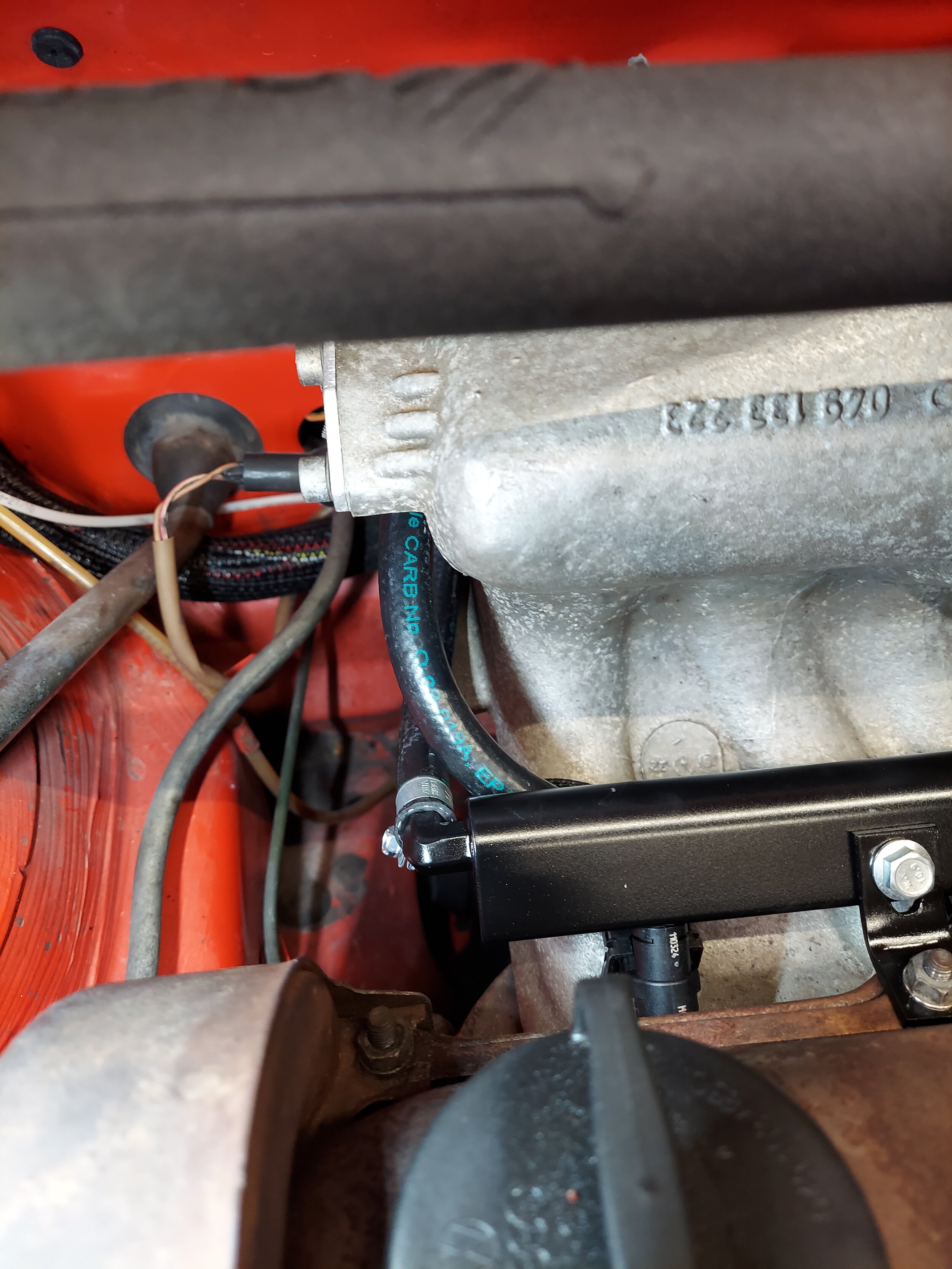
Step 27
Install map sensor to manifold vacuum
-

Step 28
Time to start installing the new wiring harness. This can be run out the original cis wiring hole from the inside the car out to the engine bay (recommended for na, supercharged or nitrous installs), or is long enough to run across the knee bar and out the driver side firewall (recommended for turbo apps). The original wire harness firewall grommet will be split on one side and reused on the new harness
Note : On MK2 Jetta/Golf/Scirocco the harness will route through the rain tray. On some Sciroccos the hole is only about 1” round and will need to be trimmed open to 1 1/4” or a little larger
-

On cars with the 1 1/4” firewall hole the connectors need to be fed into the engine bay in a specific order
-

Harness running across kneebar
-

Harness running across kneebar
-

Harness running out driver side firewall
Note : On MK2 Golf/Jetta/Scirocco the afr gauge and new fuel pump power wire will run through the small 1/2”-5/8” hole
-

Harness running out original cis wiring hole on passenger side firewall.
-

Step 29
Hook up new fuel pump power feed wiring to the pump. The old pump wiring can stayed hooked up to the pump as well. Remove the old fuel pump relay (it will not be used). This can be run direct to the fuel pump (which is recommended, especially for turbo apps). Or can be plugged into the fuse panel when the old fuel pump relay is removed.
Note : Mk2 Golf/Jetta apps are only supported right now by hooking up the wiring to the FPR socket on the fuse panel. I am working on finding the correct connectors and pins to make this PNP at the pump
-

Supplied ground wire for fuel pump grounded to body. Only needs to be hooked up if running the new fuel pump wire directly to the fuel pump. Make sure you clean the grounding surface to the body
-

If opting to not run the new fuel pump power wire to the fuel pump, the wire can be simply plugged into the old fuel pump socket on the fuse panel. It will go into the socket that pin 87 on the fuel pump relay went into.
-

Fuel pump power wire plugged into FPR pin 87 on fuse panel
Note : Depending on the year of your car your fuse panel will look different (CE1,CE2), but this step will remain the same. Just follow the pins on your original relay
-

Step 30
Remove cold start relay/hot start relay. Can be located on the fuse panel or steering column. The FPR and CSR are both not used. They are going to be located in a few different spots depending on the app. Some are on or above the fuse panel.
Note : This style relay jumper block will only be on certain older car cars usually 82 and down.
If you do not remove the CSR it will make a buzzing noise due to being fed a tach signal on the new setup
-

Step 31
Install airbox block off plate (reuse old Oring) and remove the flapper arm disc. You can remove the entire flapper arm assembly, but it is not necessary and will gain no performance.
-

Step 32
Hookup labeled wire connectors to their sensors.
Note : If using the stock cis aux idle valve on the back of the intake manifold DO NOT hook the IAC connector to that. The IAC connector is for a true IAC valve like aba or 16v which can be optionally installed in place of the aux idle valve
-

Remove the old cis o2 sensor and install the new wideband sensor. If the old sensor is seized, you can leave it in place and have the supplied bung welded into the exhaust.
I have pre-calibrated the wideband o2 sensor with the lc2. If you power on the lc2/car with the o2 sensor disconnected from the lc2, the sensor will need to be removed from the exhaust and recalibrated. Calibration instructions are in the innovative manual provided as well as diagnostic codes for the gauge if there is a problem with the system
-

Step 33
Reinstall battery and hook up the 2 red fused power wires to the positive terminal and hook up the 1 black wire to negative terminal. This will complete the hardware install
-

Plug in the data cable to the microsquirt ecu and use the usb to serial adapter to plug into your laptop you're going to be tuning with. Depending on your laptop software you may need to download a driver for the usb to serial adapter to work
Note : On MK2 Golf/Jetta/Scirocco the headphone jack side of the cable will feed from inside the car out to the rain tray through the same 1/2”-5/8” hole the afr gauge/fuel pump wires come through. There is a piece of marine shrink wrap included to seal the headphone jack/com port once connected
-

Open the tuner studio software. link http://www.tunerstudio.com/index.php/downloads
This is the main page. Click create new project
-
Add project name. Click detect, this will search for the ecu. Key must be in on position to power up ecu and the data cable hooked to the ecu with serial to usb adapter hooked up to your laptop/tuning computer. If it does not detect, you will probably need to download the driver file for the usb adapter or change the communication baud rate (it is usually a driver file missing). I have made sure to bench tested all the cables, sensors, and harness in your kit directly with your ecu before shipping.
-

Once ecu has been detected, click accept, then click next
-

Next screen is Configuration settings. These do not need to be touch, the default settings are good. Click next
-

Next screen is Communication settings. Click test port, it should come back successful. Click next
-

Next screen is dashboard. This is the gauge display you will see once the ecu has been connected to tuner studio. You can leave it on default, but I recommend downloading the dashboard display I have emailed over with the base file copy and installing that. To do that check other, then click the 3 dots in the right corner to browse for the file download.
Note: If using the lite free version this option will not work
-

Once new dashboard has been downloaded, you’ll see there’s a lot more gauges for viewing data added. Click finish and that will conclude the initial setup
-

You will now be able to see your dashboard gauges. If you have chosen to download the custom dash display I sent over, you will notice the fuel psi gauge has a red box around it. We need to create a channel for this gauge. Click tools, add custom channel wizard
-

Transfer the information displayed in this screen shot exactly the same. Click next
-

Transfer the info in this screen shot again. Click finish
-

Now that the fuel psi gauge is setup the red box should be gone around it. Right click on the fuel psi gauge, put the cursor on sensor inputs 2, and then click on fuel psi. The fuel psi gauge should now be working and no red box around it
-
At this point your about ready to fire the car up for the first time. I would cycle the key a few times to let the fuel system build up pressure and check for any fuel leaks. Once this has been done try to start the engine. Adjustments may need to be made to the idle screw or throttle blade stop. With the engine running, check the fuel psi gauge on your dashboard. It should be at 58-62psi, if not, adjust the fuel psi regulator. To do this loosen the 17mm lock nut and turn the center stud with an 5mm allen key. Turning out/left/counterclockwise will lower psi, turning in/right/clockwise will raise psi. Snug the lock nut once psi is set, do not over tighten
-

The next step is absolutely critical, ignition timing must be checked/set with a timing light. To do this we are going to go into the the software and lock the ignition at a set degree. On the main dashboard click the Ignition Settings tab, then ignition options
-

In ignition settings, under fixed advance, switch from user table to fixed timing. Now check Timing for fixed advance (degrees), it should already be set at 10, if not type in 10 for 10 degrees, Hit burn. you should hear the car idle down some since timing has now been retarded. You can now verify that the distributor is set correctly by checking timing with a timing light. The timing light and marks should read/line up 10*, if not adjust the distributor. Once timing is set and verified, go back into ignition settings and switch from fixed timing back to user table, hit burn.
AGAIN DO NOT SKIP THIS STEP!!!!!
-

Now that timing is set, and the car should be warmed up, it’s time to start dialing in the fuel with the autotune feature. On the main dashboard click Tune Analyzer Live, then advanced settings. The autotune won’t work unless the coolant temp is above the minimum clt temp. This should be set to 140-160*. If your engine is above those temps (which can be checked on the main dashboard) click start autotune. You will see the tracer moving and correcting cells in the fuel map. Click on the status bar, you will see in cell weighting the chart changing color, once you see dark green in those areas, fuel should be dialed in to the settings on the afr chart (I have preset the afr settings in the fuel settings)
-
Once idle afr is dialed in its time to start driving the car and letting the autotune do its magic. Drive the car around, IN A NORMAL CONTROLED MANNER, around town and on the highway. You will see colors start popping up in the cell weighting area. Once the cell weighting is dark green in those areas on the you can start doing full throttle pulls. Note that the tracer will only hit certain load areas, this is normal. Keep an eye on your o2 gauge to see where afr is at.
AFR targets: Idle 12.8, Cruising and around town 13.8-14.5, full throttle NA engines 12.5.
Full throttle in boosted engines 11.2-11.8.
Start on the lowest boost setting possible and work your way up.
On boosted apps don’t go for broke and just start hammering it full throttle, do easy progressive pulls so the ecu can correct the fuel. If you see lean mixture, get out of the throttle, wait a few seconds then do another pull. On turbo apps pay attention to your Intake temps when doing pulls. Try not to go over 120*f. When your finished tuning click apply/burn/save on ecu, then save on ecu. This will burn the autotune changes to the ecu.
Save a copy of config file as a backup as well under file, save config. Files and logs will be stored in Documents under Tuner Studio.
If you are uncertain at any time or uncomfortable with tuning, contact us and we will help get you sorted.
DONT BE STUPID, you can hurt your engine very easy with lean afr, Ping/Knock and full throttle driving like speed racer, especially under boost.
-