
This is a basic Guide to help with installation. There may be small differences over different models years, but the setup is very similar. Remember this is a standalone ecu and some tuning/setup is required.
The alt belt is often stretched on these engines. The napa brand belt are notorious for this. It is recommended a new Continental belt be installed
Part numbers: 6PK720, 99919229050, LR012663
*Disclaimer*
*Please note You are going to be touching a fuel system and fuel which is flammable. Please take all the necessary safety precautions required and have a fire extinguisher on hand. BillT Industries assumes no liabilities or responsibility for any damages that may occur during the installation and tuning of this kit. It is the sole responsibility of the end user or installer to make sure this kit is installed and tuned properly*
Software Download - Downloads (tunerstudio.com)
Ultra Software - https://www.tunerstudio.com/index.php/products/tuner-studio/tsarticles/119-tunerstudio-30-feature-matrix
The lite free version of ms is very limited. I recommend purchasing/registering the Ultra software for full feature and logging access all in one program
-
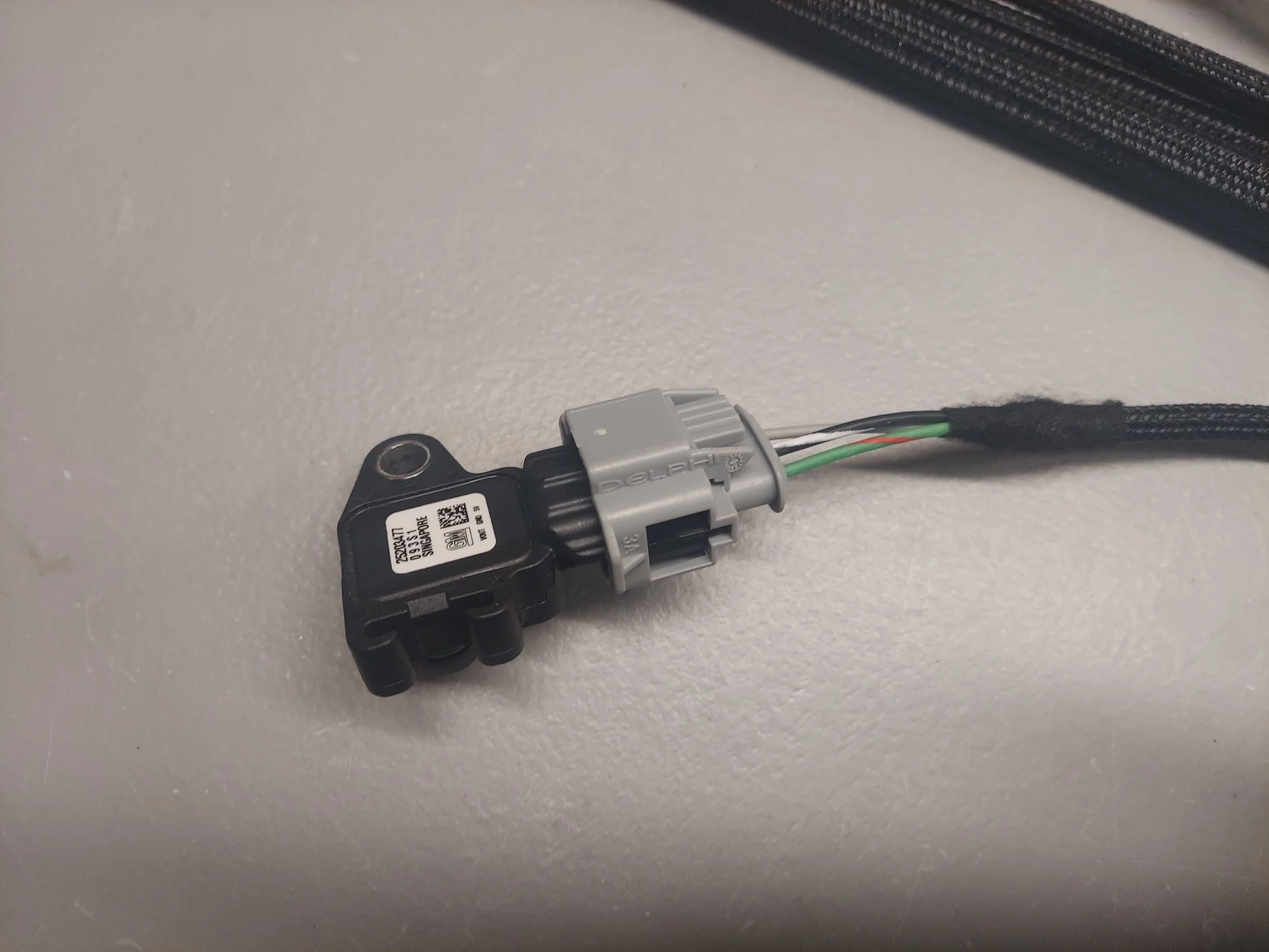
This is the map sensor. It will connect to your klr box vac/boost hose
-
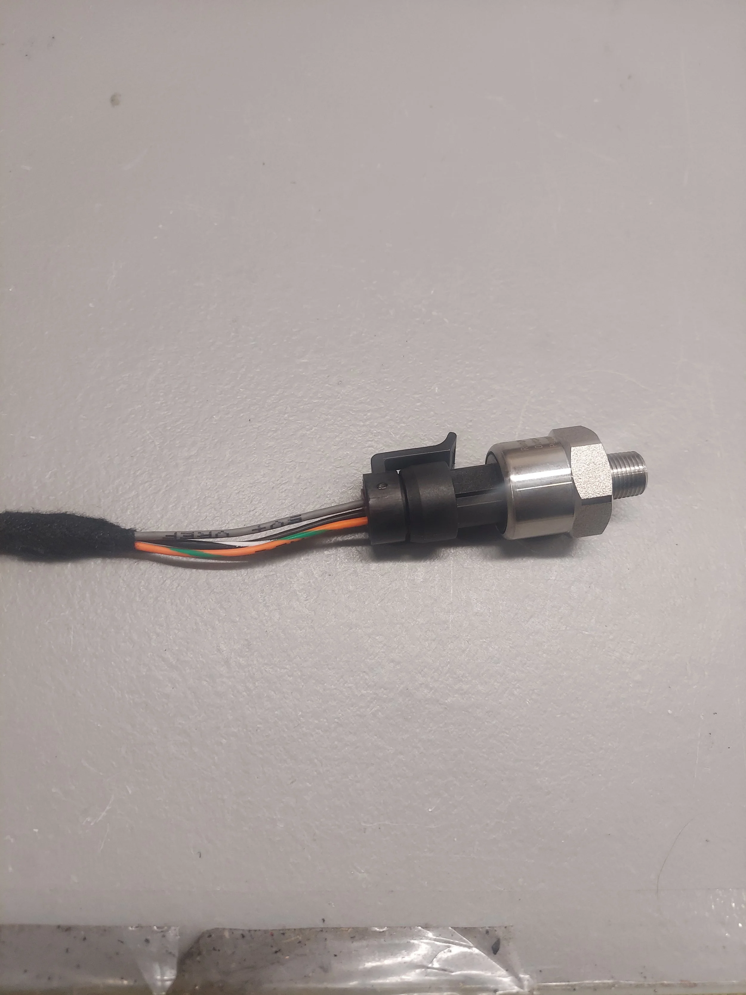
This is the optional fuel psi sensor. This will connect to the end of your fuel rail test port. You will need an adapter to connect this. Sensor thread is 1/8npt
-

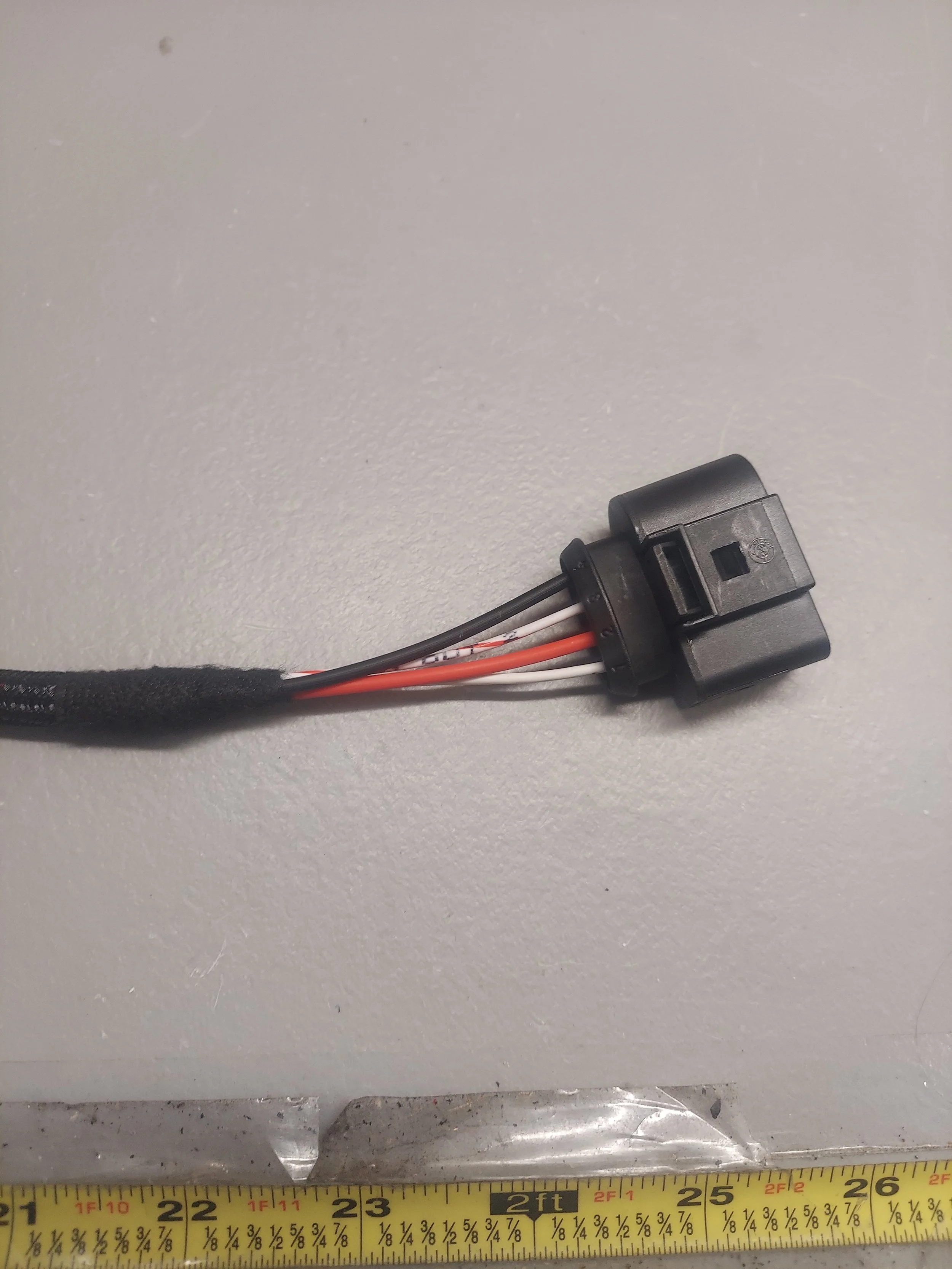
This is the crank trigger extension harness. This will connect to the crank trigger sensor by the crank pulley and to the original engine harness connector for the speed sensor.
You will reuse your original crank speed sensor
The crank trigger for speed pick up is the sensor that reads the flywheel ring gear teeth. It is the senor further away from the engine closer to the firewall
-
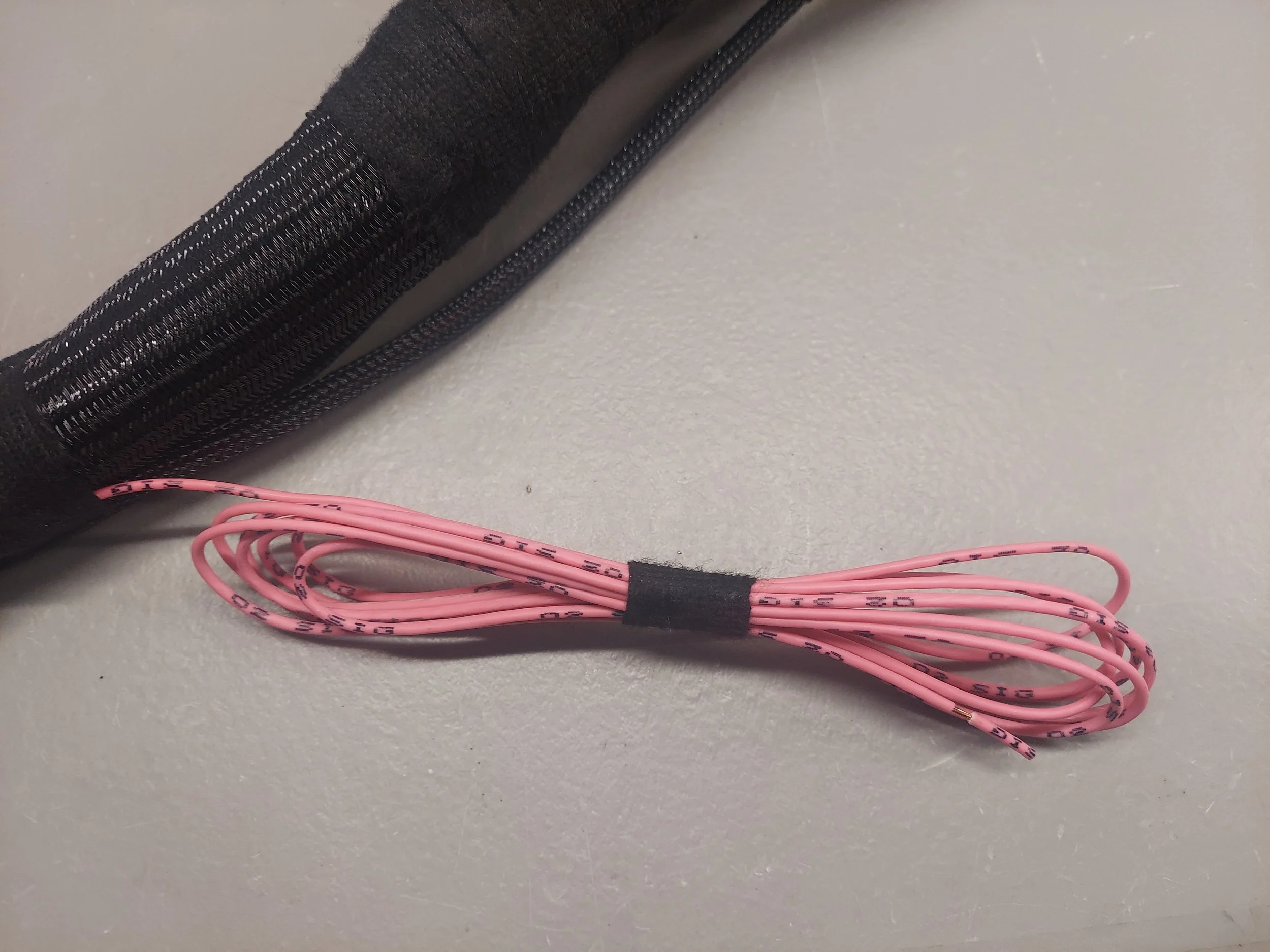
This is the o2 sensor signal wire. If you already have a wideband o2 sensor/gauge installed, this wire will go to analog output wire on your gauge/controller.
Full kits that come with the wideband already have this wired in.
-
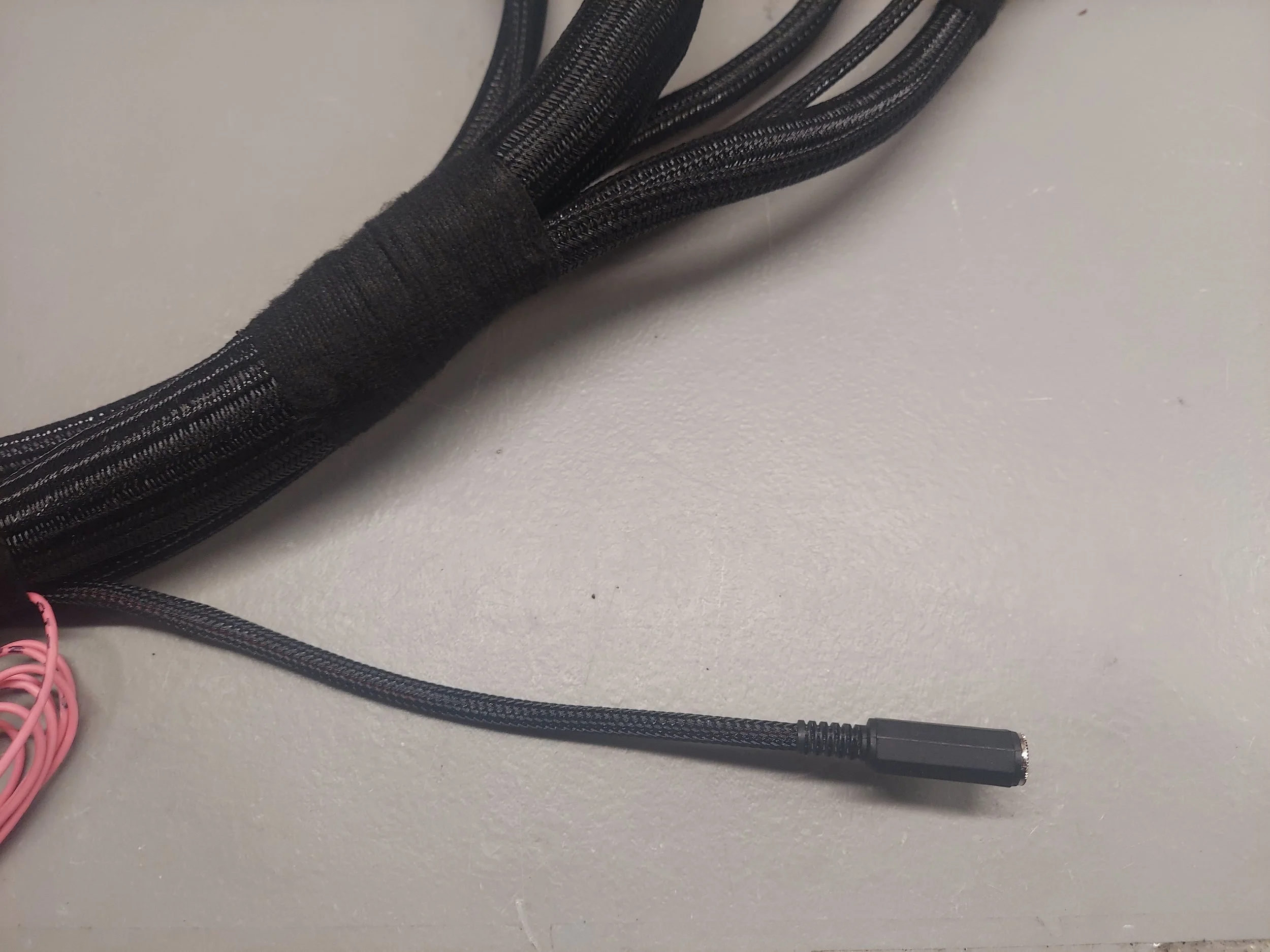
This is the data com to the ecu. There will be a tuning cable along with an rs232 to usb adapter cable
-

These wires are not used on most apps. These are for extra options like canbus data, cam sensor, extra injectors
-

This is the adapter from the afm plug to new iat sensor when deleting the afm
-
This connector is for a waste coil pack option
-
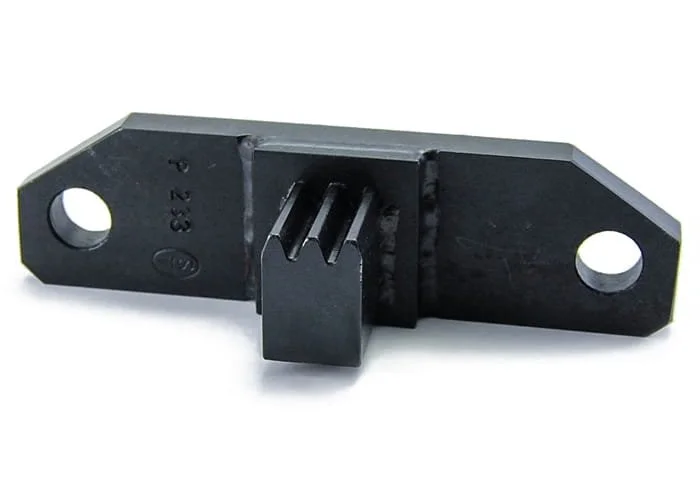
Before beginning the install you will need the 944 flywheel lock tool that goes into the bellhousing in the starter location. You’ll need this tool in order to remove/install the crankshaft pulley bolt to proper spec.
You will also need a voltmeter and a timing light for the ecu setup.
-
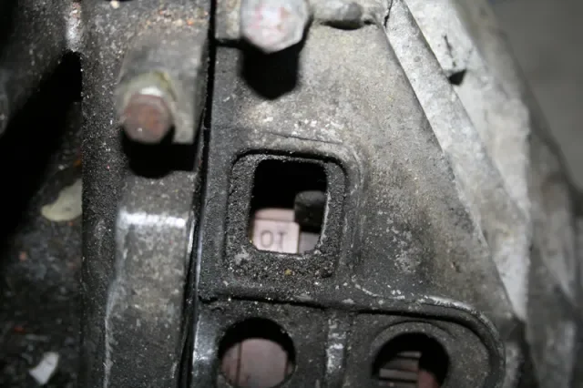
Set the engine at tdc going by the marks on the flywheel and bell housing.
The ot line should line up with the pointer on the bell housing. It can be difficult to see with the 944 wiring in the way.
It is ok if you have to rotate the engine slightly off tdc to get the flywheel lock tool installed
Note you can remove the rear crank sensor/speed sensor now also. It will be reused for the crank trigger wheel
-
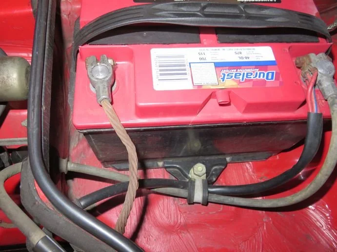
Disconnect the battery. Your going to be removing the starter to install the flywheel lock tool so this must be done.
Follow Pelican Parts write up for the starter removal and tool install
-
Next step is to remove the engine splash shield and accessory belts for power steering and alt/ac.
Follow the Pelican write up link
-
With the flywheel lock in place and belts off, remove the crankshaft bolt. It should be a 24mm or 15/16 socket. The power steering pulley will now be removed
-
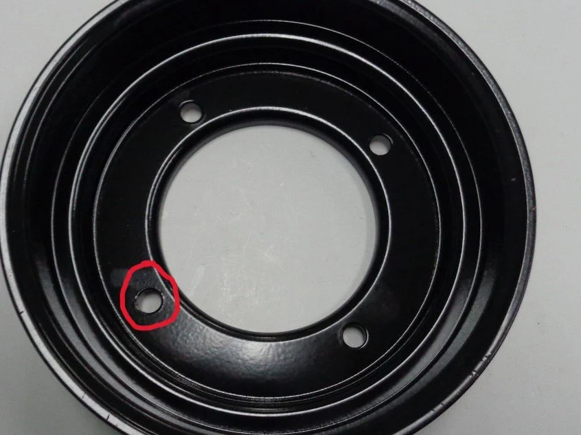
Mark the location of the lower right bolt hole on the crankshaft alternator pulley (this bolt is pointed towards the power steering pump).
Now remove the 4 bolts and the pulley. They should be a 10mm socket.
Mark the crankshaft timing belt gear bolt hole as well in the same location as the crankshaft alternator pulley. The missing tooth on the trigger wheel will line up with these bolt holes
-

Test fit the trigger wheel on the back side of the crankshaft alt pulley. It is a sung fit. Some minor filing or sanding may be required on the trigger wheel or pulley.
Mark the trigger wheel missing tooth bolt hole so install is easier. It is hard to see the missing tooth once behind the timing cover
-
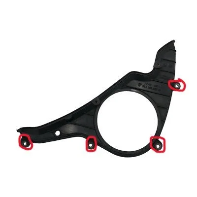
Remove the 4 outer bolts for the lower timing cover. Should be a 10mm socket. The lower timing cover does not have to come off.
You will separate the timing cover slightly and slide the crank trigger wheel behind the cover so it can sandwich in-between the timing gear and crank alt pulley.
The marked missing tooth bolt hole will line up with the marked right lower timing gear bolt hole that was marked earlier
-
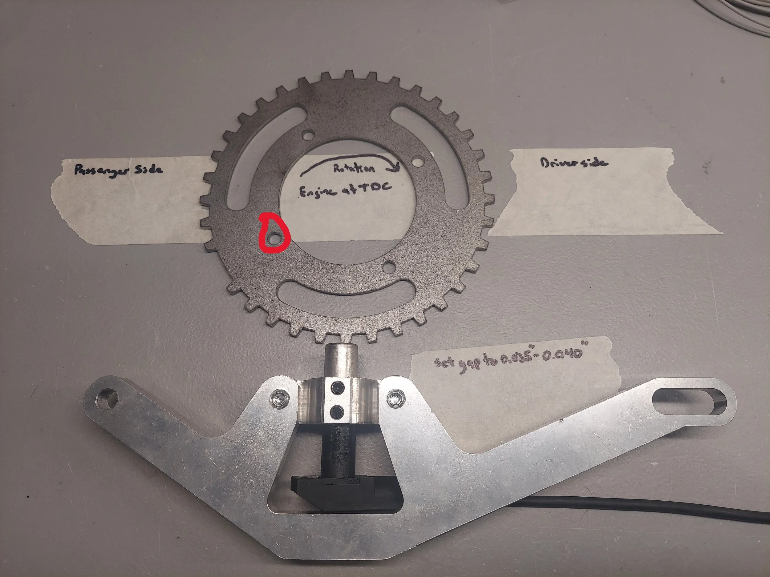
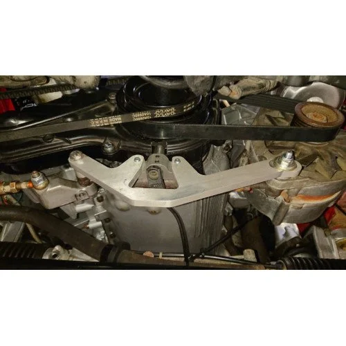
Trigger wheel missing tooth hole that should line up the timing gear marked hole and crank marked hole from earlier.
Note the sensor mount and bracket orientation/assembly.
You will be reusing your original crank speed sensor
-
Install the crank alt pulley so all the marks made on the timing gear and missing tooth line up. The missing tooth will point towards the power steering pump. I will use blue locktite on the bolts for the pulley on final assembly.
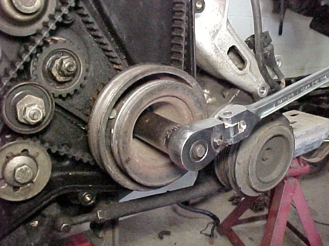
With the pulley install test fit the trigger bracket to mark the hole for the crank sensor to be drilled. Put the spacers on the bracket like in the next picture with the alt tensioner rod.
Take care when drill/cutting to not hit to trigger wheel or timing belt. You can remove the trigger wheel if wanted while test fitting/drilling. A dremel works well for this
-
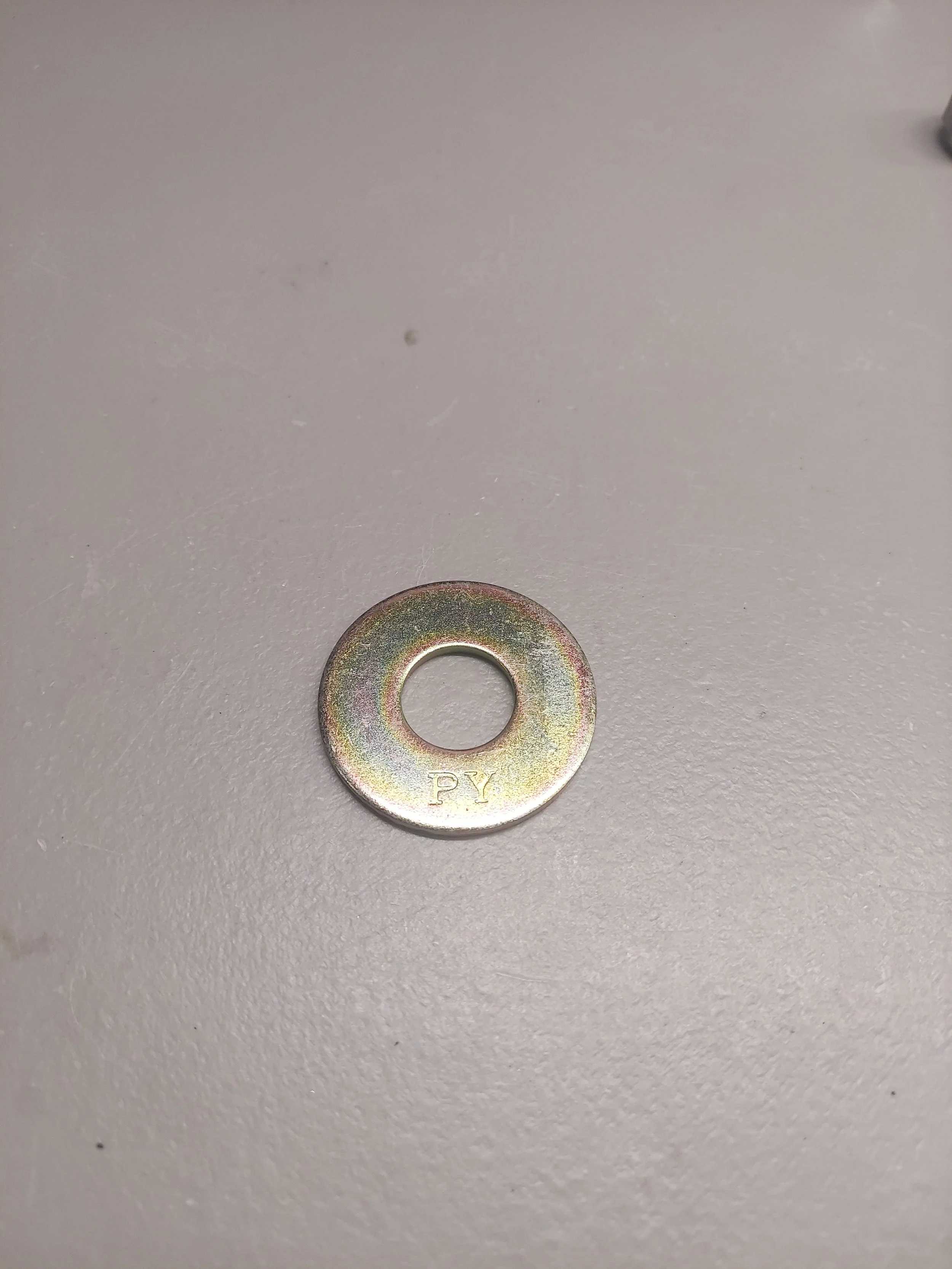
The alternator pulley needs to be removed to install the big washer between the alt fan and pulley.
-
New hardware has been supplied with the kit. The holes are often stripped on the alt or bracket for the tension rod to mount to. I have included longer bolts and spacers if needed.
Once test fitting has been done the sensor gap needs to be set at 0.035”-0.040”
Using a vernier caliper makes this process easier. I like to use blue locktite on the set screws for the sensor. Do not over tighten the set screws into the sensor
The wire for the sensor will run up between the block and alternator
-
Reinstall the timing cover bolts
Reinstall the the power steering pulley and torque the crank bolt to spec 155ft/lbs. I like to use red locktite on the crank bolt.
Install and tension your acc belts. The lock tool can now be removed and the starter reinstalled
-
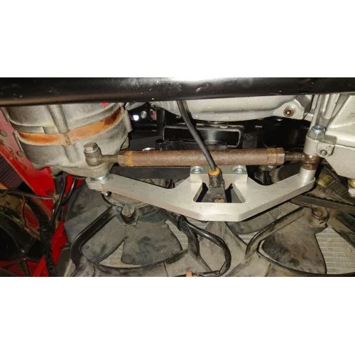
The crank trigger extension harness will run under the intake manifold toward the alternator. You can tape the harness to a long zip tie or old coat hanger to help snake it under the manifold
-
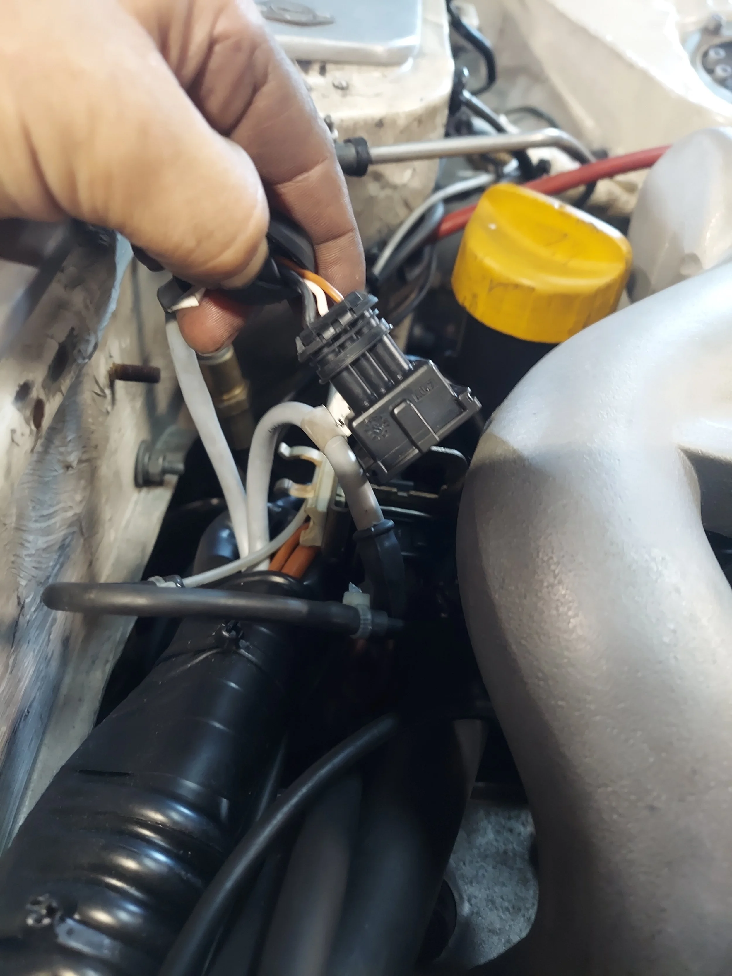
If removing the stock afm, the new intake air temp sensor needs to be mounted into the intercooler pipe. The bung needs to be welded to the intercooler pipe going to the throttle body. It needs to be close enough for the old afm plug to connect to. This is usually closes to the intercooler coupler with a stock airbox.
The afm wires for the iat need to be removed from the connector. Pin 4 yellow/red wire will go to pin 2 on the new connector. Pin 1 green wire will go to pin 1 on the new connector
We now have a jumper harness for this so no depinning is required
-

The stock dme and klr box are located behind the carpet footwell on the passenger side. These will be removed and the pnp adapter with ecu installed
-

The klr vac hose will be removed and hooked up to the new 4bar map sensor. I have installed a new vac hose on the sensor. I like to use 3 zip ties to secure the hose to the map sensor
-
If installing the optional fuel psi sensor a small hole needs to be made in the engine harness body grommet to get the sensor plug through. The sensor wire can run under the fuel rail cover for the injector wiring
-
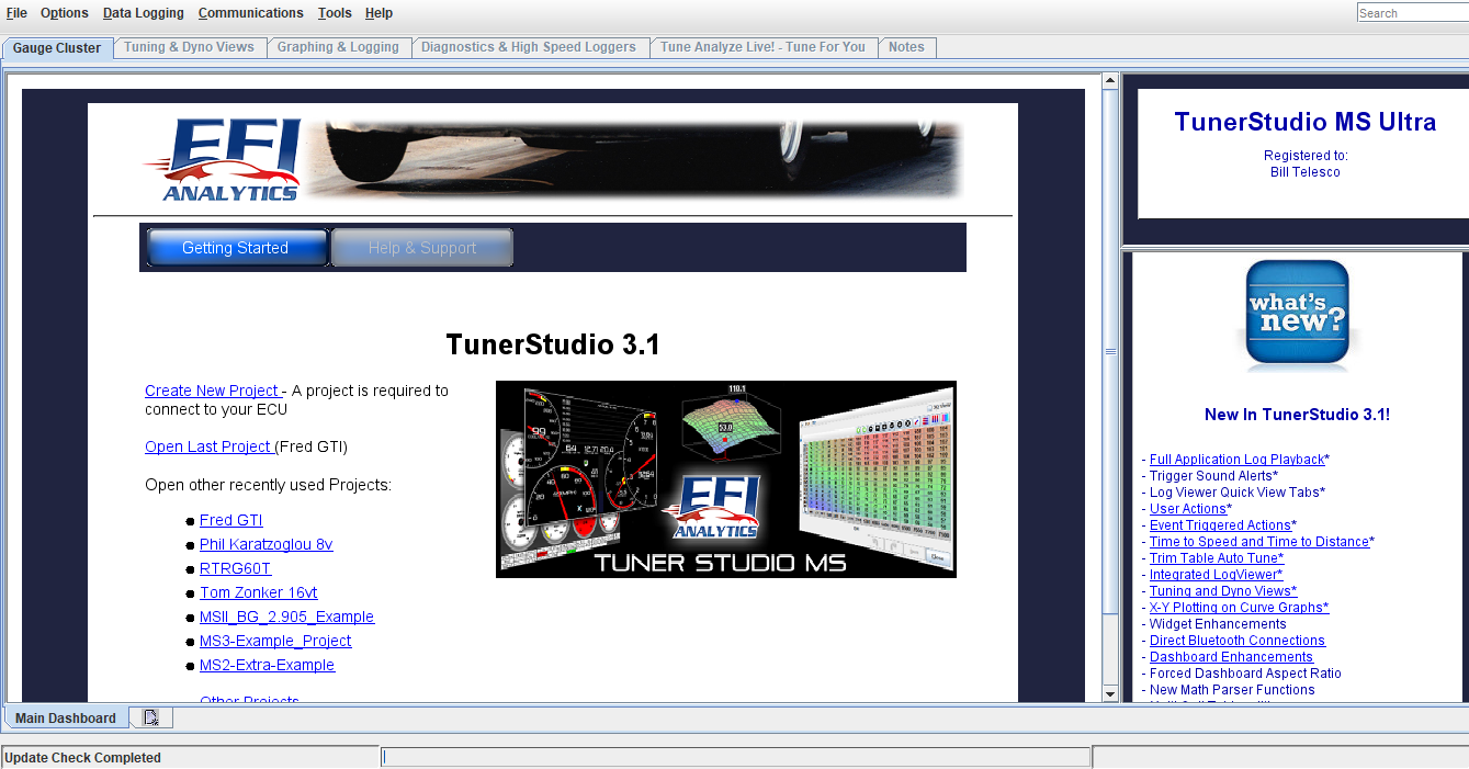
Open the tuner studio software. link http://www.tunerstudio.com/index.php/downloads
This is the main page. Click create new project
-
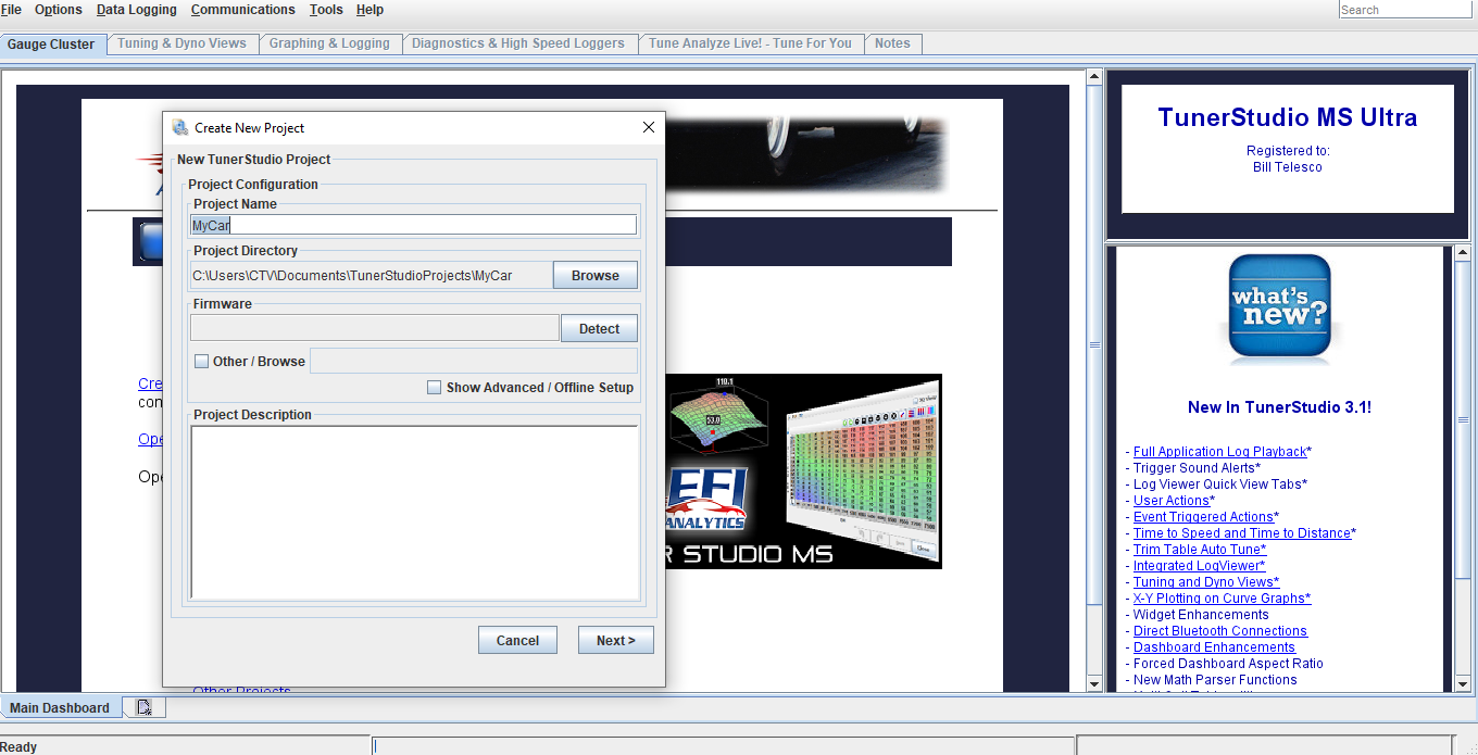
Add project name. Click detect, this will search for the ecu. Key must be in on position to power up ecu and the data cable hooked to the ecu with serial to usb adapter hooked up to your laptop/tuning computer. If it does not detect, you will probably need to download the driver file for the usb adapter or change the communication baud rate (it is usually a driver file missing). I have made sure to bench tested all the cables, sensors, and harness in your kit directly with your ecu before shipping.
-
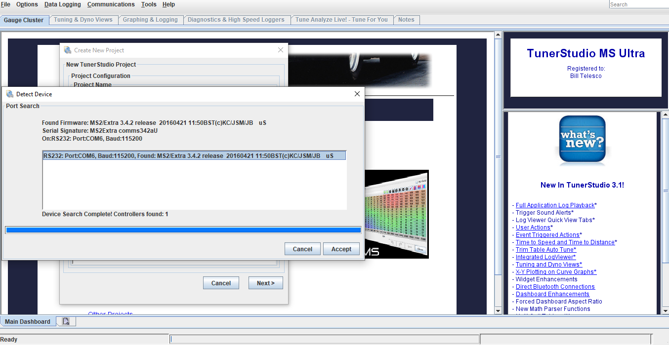
Once ecu has been detected, click accept, then click next
-
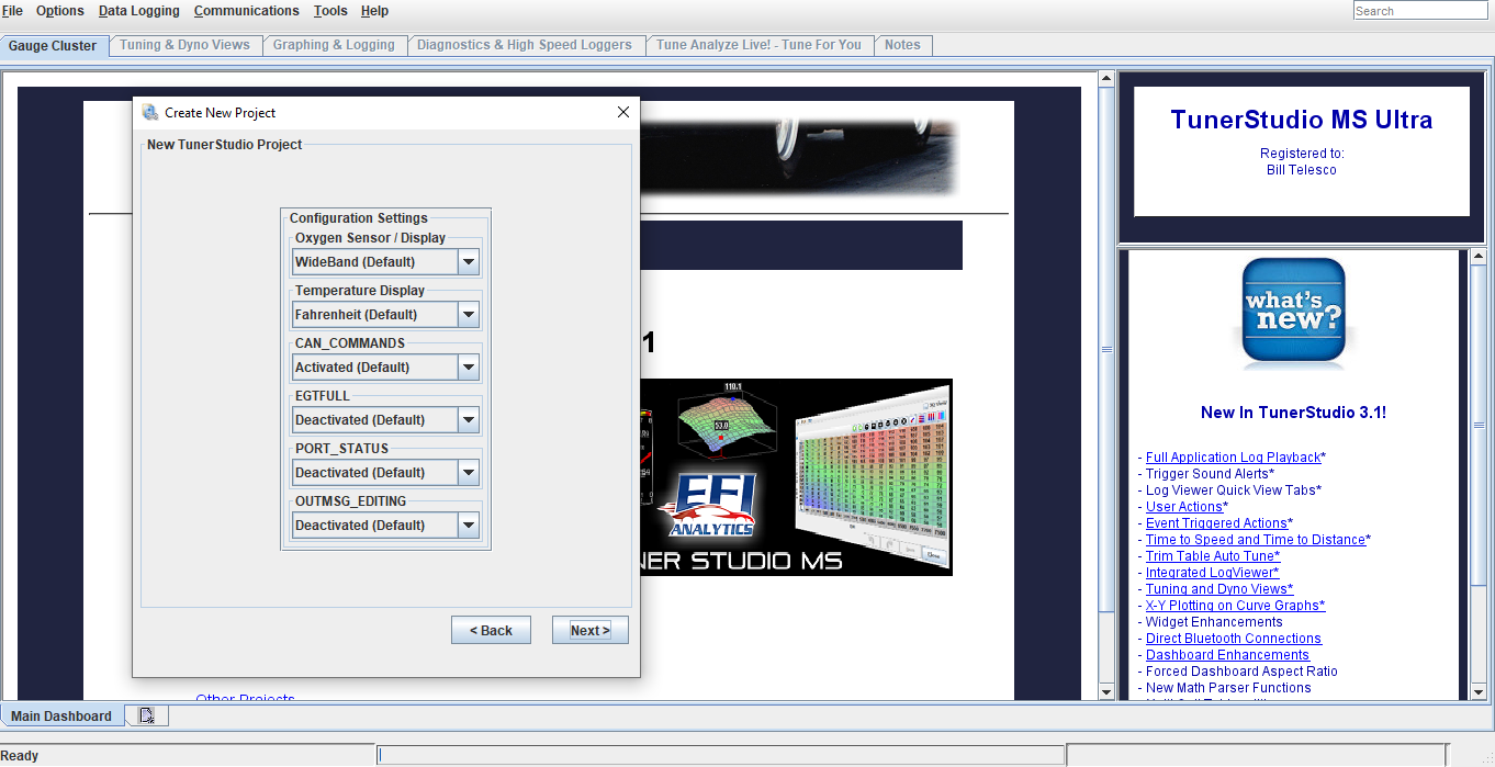
Next screen is Configuration settings. These do not need to be touch, the default settings are good. Click next
-
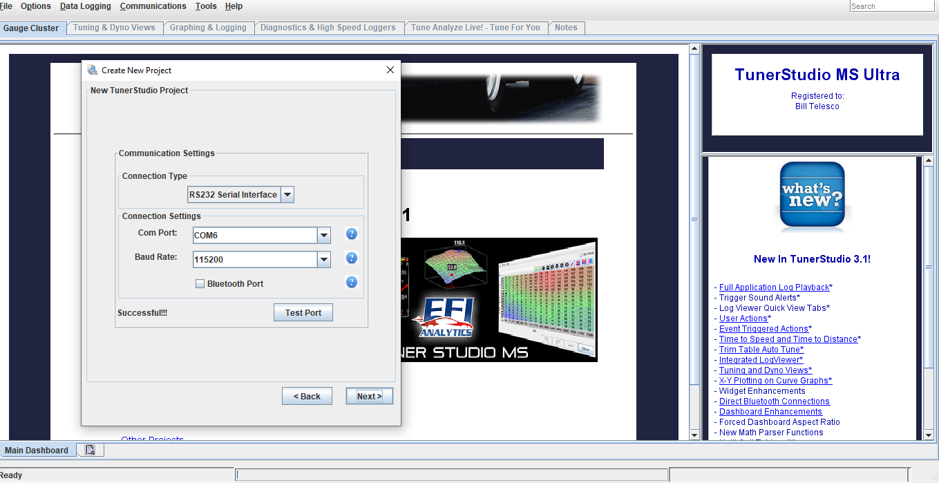
Next screen is Communication settings. Click test port, it should come back successful. Click next
-
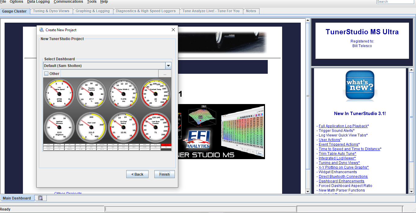
Next screen is dashboard. This is the gauge display you will see once the ecu has been connected to tuner studio. You can leave it on default, but I recommend downloading the dashboard display I have emailed over with the base file copy and installing that. To do that check other, then click the 3 dots in the right corner to browse for the file download.
Note: If using the lite free version this option will not work
-
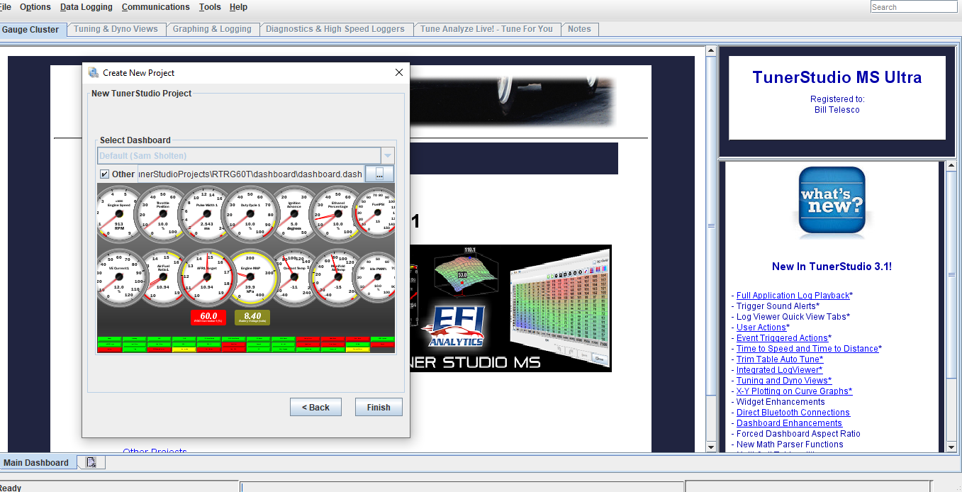
Once new dashboard has been downloaded, you’ll see there’s a lot more gauges for viewing data added. Click finish and that will conclude the initial setup
-
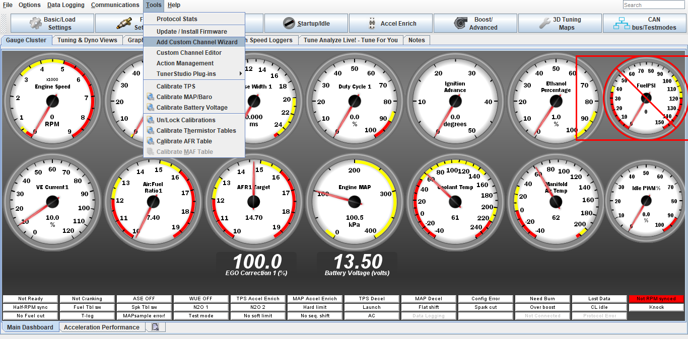
You will now be able to see your dashboard gauges. If you have chosen to download the custom dash display I sent over, you will notice the fuel psi gauge has a red box around it. We need to create a channel for this gauge. Click tools, add custom channel wizard
-

Transfer the information displayed in this screen shot exactly the same. Click next
-

Transfer the info in this screen shot again. Click finish
-
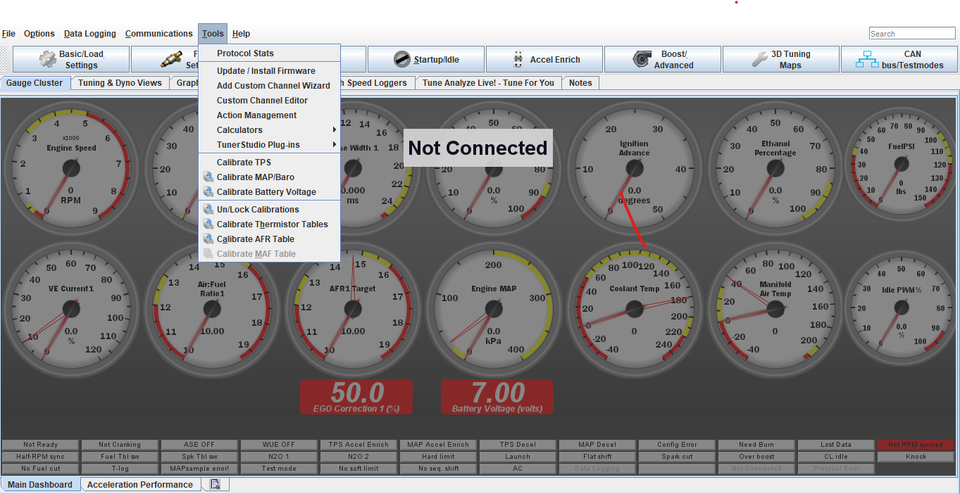
Next we’ll do a base setup for the tps sensor. Click Tools, Calibrate TPS
There is already a base setting in the ecu, but this should be verified
-
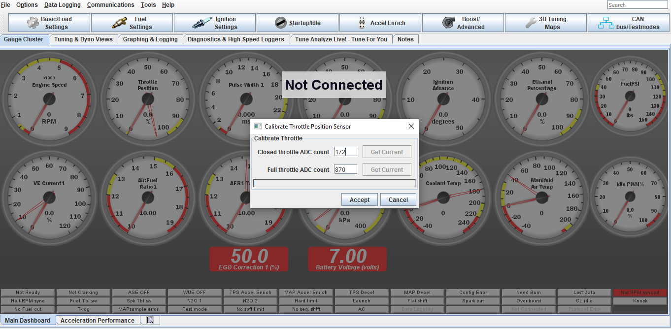
To cal the TPS closed throttle click get current next to closed throttle count.
To cal tps full throttle push throttle pedal to the floor and click get current.
You should verify also that the throttle body is opening fully with the pedal depress.
This step will be revisited once the engine is running and idle adjustments are made with the idle screw and throttle stop screw on the throttle body
-
At this point your about ready to fire the car up for the first time. I would cycle the key a few times to let the fuel system build up pressure and check for any fuel leaks. Once this has been done try to start the engine.
Adjustments may need to be made to the idle screw or throttle blade stop. With the engine running, check the fuel psi gauge on your dashboard. It should be close to your installed regulator be it a 3bar/43psi or 4bar/60 psi.
If your have an adjustable style you can set it to your desired psi, usually 3 or 4bar is good
-
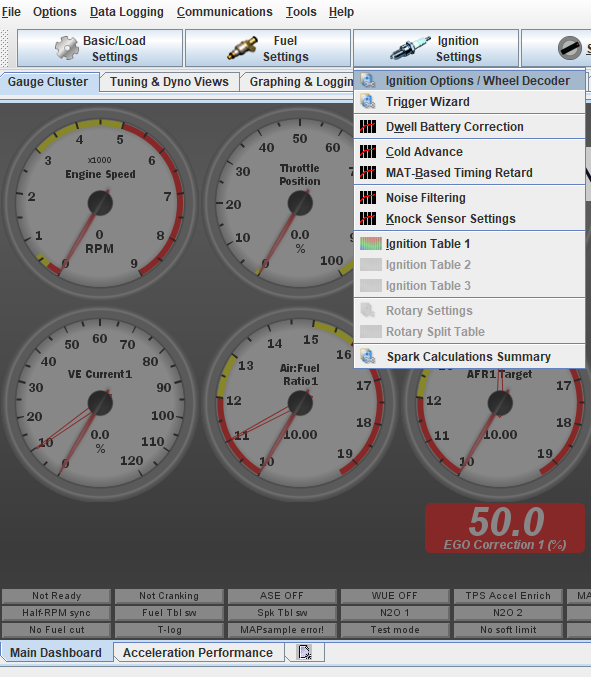
The next step is absolutely critical, ignition timing must be checked/set with a timing light. To do this we are going to go into the the software and lock the ignition at a set degree. On the main dashboard click the Ignition Settings tab, then ignition options
-
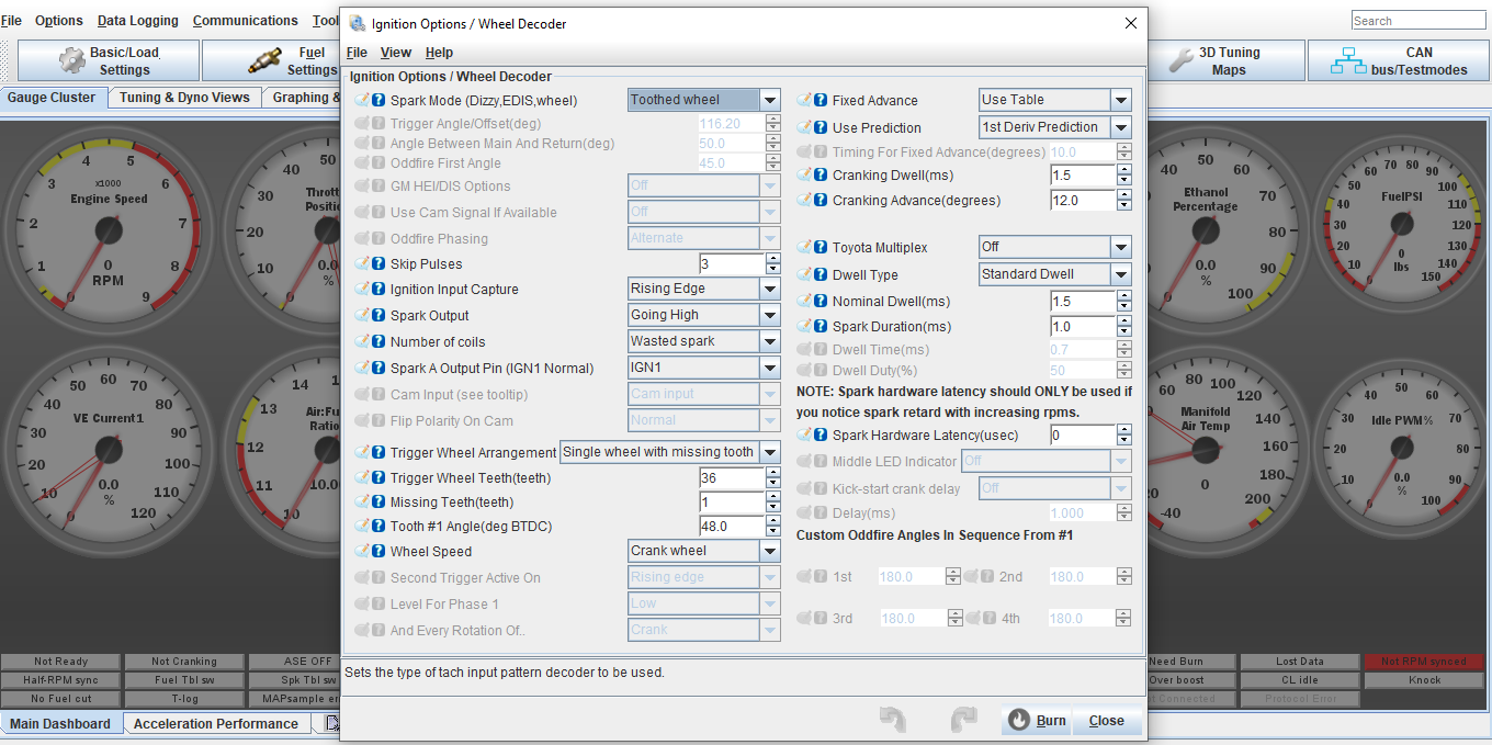
In ignition settings, under fixed advance, switch from user table to fixed timing. Now check Timing for fixed advance (degrees), it should already be set at 10, if not type in 10 for 10 degrees, Hit burn. You should hear the car idle down some since timing has now been retarded. You can now verify that the Tooth #1 angle is set correctly by checking timing with a timing light. The timing light and marks should read/line up 10*, if not adjust the Tooth #1 angle setting until the timing marks line up on the flywheel/bellhousing. Once timing is set and verified, go back into ignition settings and switch from fixed timing back to user table, hit burn.
AGAIN DO NOT SKIP THIS STEP!!!!!
-
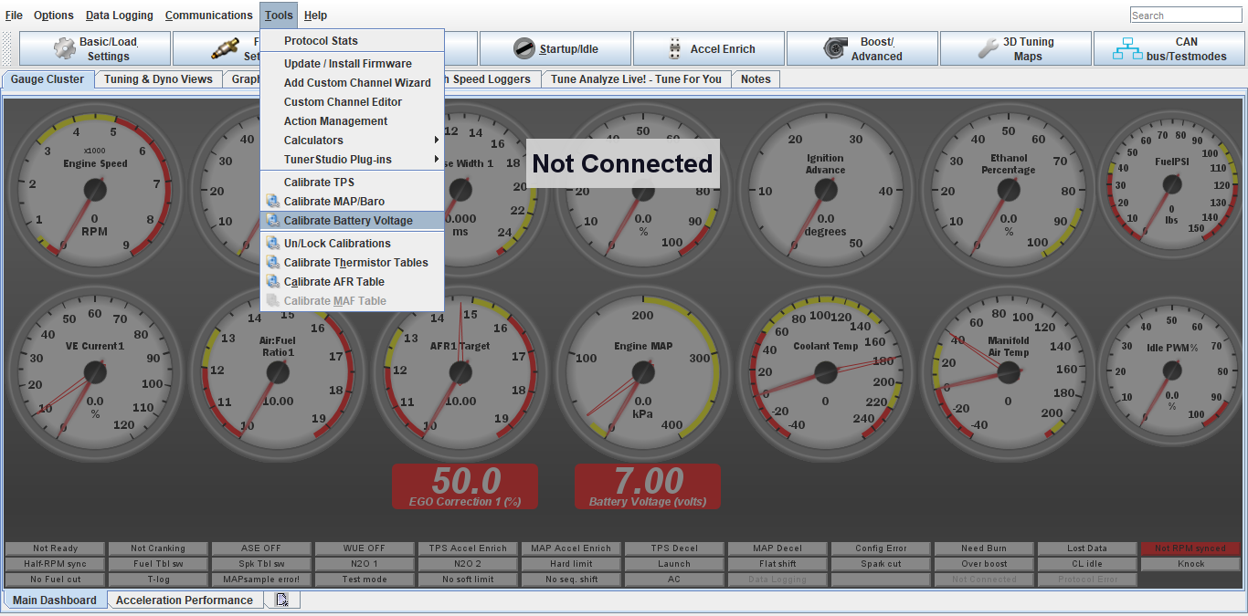
Next is to check the battery voltage calibration. This will directly affect the fuel mixture as a whole.
Click tools, Calibrate Battery Voltage
-
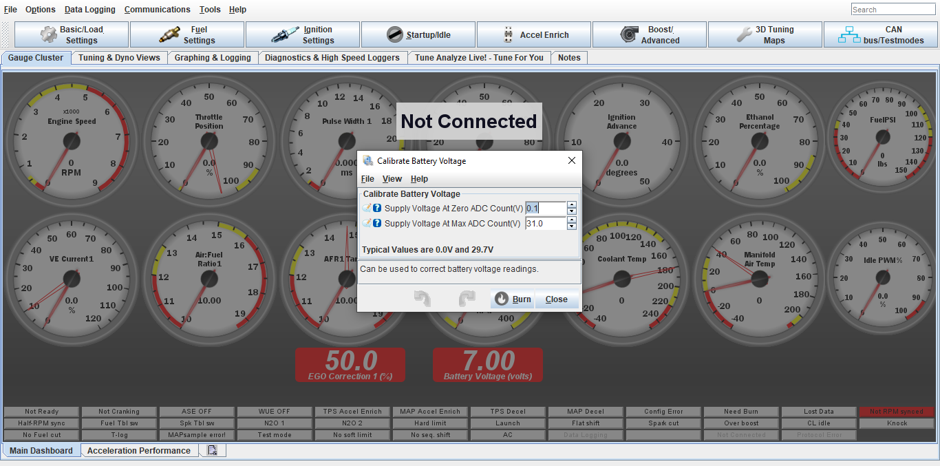
Using a voltmeter, check at the battery what voltage is and compare to the battery voltage reading on the ecu dash display.
DO NOT use the dash/center console gauge as a reading.
Adjust the Supply Voltage Max up/down if needed. The ecu battery voltage will be always fluctuating, so just get it close to the voltmeter reading
-
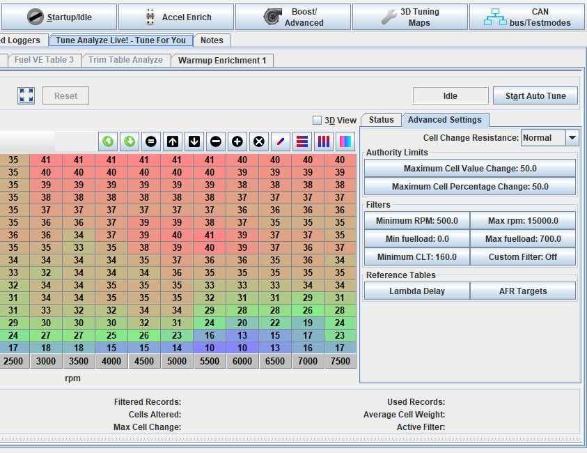
Now that timing is set and battery cal checked, the car should be warmed up and it’s time to start dialing in the fuel with the autotune feature. On the main dashboard click Tune Analyzer Live, then advanced settings. The autotune won’t work unless the coolant temp is above the minimum clt temp. This should be set to 140-160*. If your engine is above those temps (which can be checked on the main dashboard) click start autotune. You will see the tracer moving and correcting cells in the fuel map. Click on the status bar, you will see in cell weighting the chart changing color, once you see dark green in those areas, fuel should be dialed in to the settings on the afr chart (I have preset the afr settings in the fuel settings)
-
Once idle afr is dialed in its time to start driving the car and letting the autotune do its magic. Drive the car around, IN A NORMAL CONTROLED MANNER, around town and on the highway. You will see colors start popping up in the cell weighting area. Once the cell weighting is dark green in those areas on the you can start doing full throttle pulls. Note that the tracer will only hit certain load areas, this is normal. Keep an eye on your o2 gauge to see where afr is at.
AFR targets: Idle 12.8 on most 8v apps/ 13.5 idle on 16v apps, Cruising and around town 13.8-14.5, full throttle NA engines 12.5-12.8.
Full throttle in boosted engines 11.2-11.8.
Start on the lowest boost setting possible and work your way up.
On boosted apps don’t go for broke and just start hammering it full throttle, do easy progressive pulls so the ecu can correct the fuel. If you see lean mixture, get out of the throttle, wait a few seconds then do another pull. On turbo apps pay attention to your Intake temps when doing pulls. Try not to go over 120*f. When your finished tuning click apply/burn/save on ecu, then save on ecu. This will burn the autotune changes to the ecu. Turn the autotune off when done.
Save a copy of config file as a backup as well under file, save config. Files and logs will be stored in Documents under Tuner Studio.
If you are uncertain at any time or uncomfortable with tuning, contact us and we will help get you sorted.
DONT BE STUPID, you can hurt your engine very easy with lean afr, Ping/Knock and full throttle driving like speed racer, especially under boost.
-
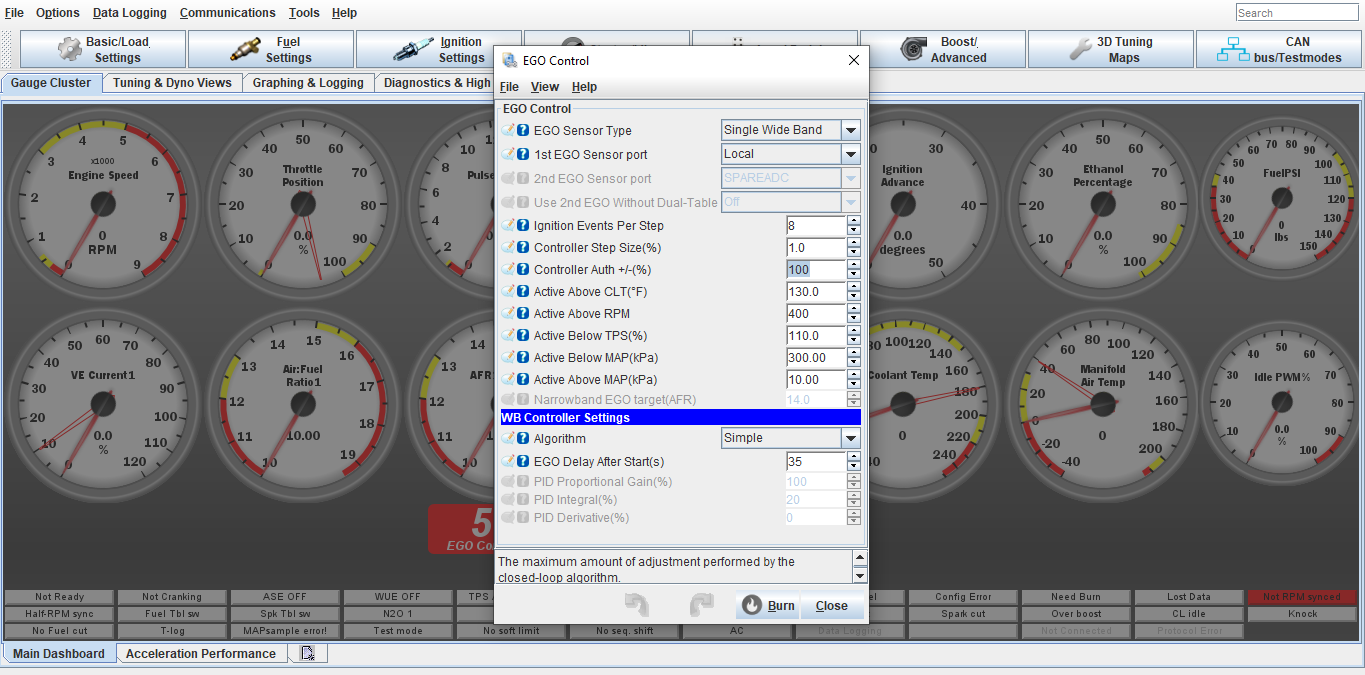
Once your warm engine tune has been complete we can turn the EGO/O2 correction control percentage down. It has been set to 100% in order to make tuning easier.
Go into Fuel Settings, Ego Control, and turn Controller Authority down to 20%
Click Burn
-

If your setup is turbo and using the electronic boost control, we can setup the safeties and boost control.
Click Boost/Advance tab, Boost Control Settings
-
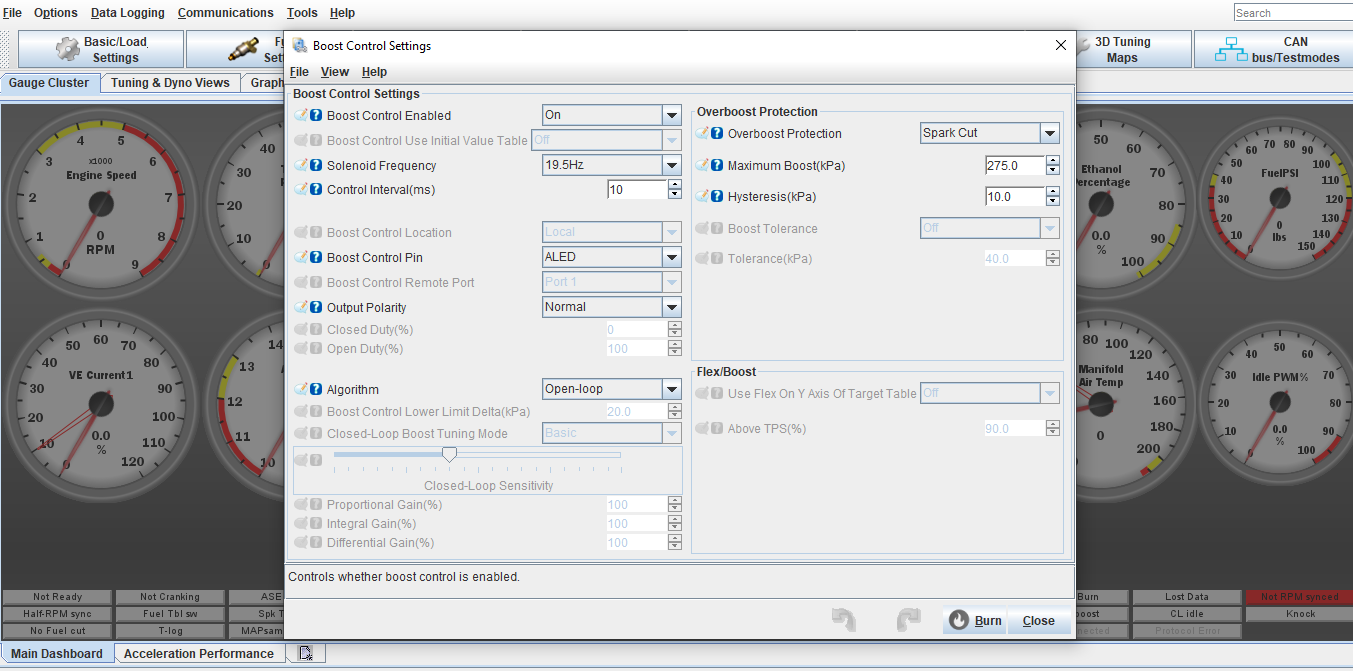
Copy the settings on this screen. Work with the open loop setting first until you understand how the boost control works. From there you can setup a closed loop map if wanted.
For Over boost Protection, set this about 5-8lbs higher than the max boost you would like to run. I will usually pre set this based on our consultation about your setup
-
Next is to setup the open loop table. Click the Boost/Advance tab, Boost Control Duty Table
-
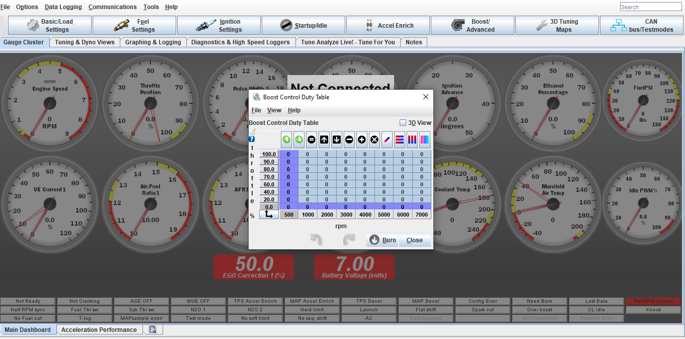
This table will be set at your discretion. This is direct duty cycle% control on the solenoid. Max duty cycle should not go over 85%.
It is best to start off with the way the table is highlighted and increase the cells in 5-10% changes until you figure out how much the % vs boost is. From there you can build a curve and ramp boost up/down vs desired power/boost level or to act as traction control for wheel spin. This is where the data logging is very useful
-
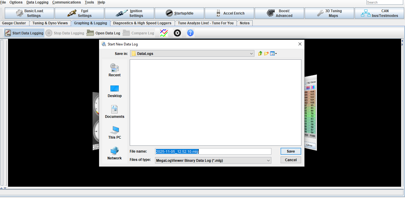
To Data log click Graphing and Logging tab, Start Data logging, Click save on the pop up screen, Click Stop Data logging when done.
The log will stay open on the screen.
To open an old data log click open data log and select your file
-
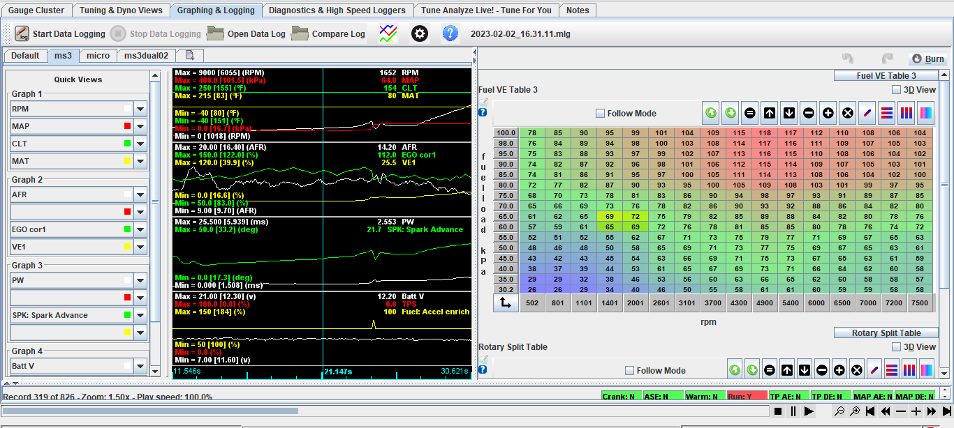
Select the data you would like to view in the log. You can save your data view list by clicking the quick view tab window in the corner. This saves time from having to setup the list every time you view a log