
This is a basic Guide to help with installation. There may be small differences over different models years, but the setup is very similar. Remember this is a standalone ecu and some tuning/setup is required.
*Disclaimer*
*Please note You are going to be touching electrical components, fuel system and fuel which is flammable. Please take all the necessary safety precautions required and have a fire extinguisher on hand. BillT Industries assumes no liabilities or responsibility for any damages that may occur during the installation and tuning of this kit. It is the sole responsibility of the end user or installer to make sure this kit is installed and tuned properly*
Software Download - Downloads (tunerstudio.com)
Ultra Software - https://www.tunerstudio.com/index.php/products/tuner-studio/tsarticles/119-tunerstudio-30-feature-matrix
The lite free version of ms is very limited. I recommend purchasing/registering the Ultra software for full feature and logging access all in one program
-
This is the optional external map sensor for the easy install kit. It will connect/tee into the vac line on the intake manifold
-

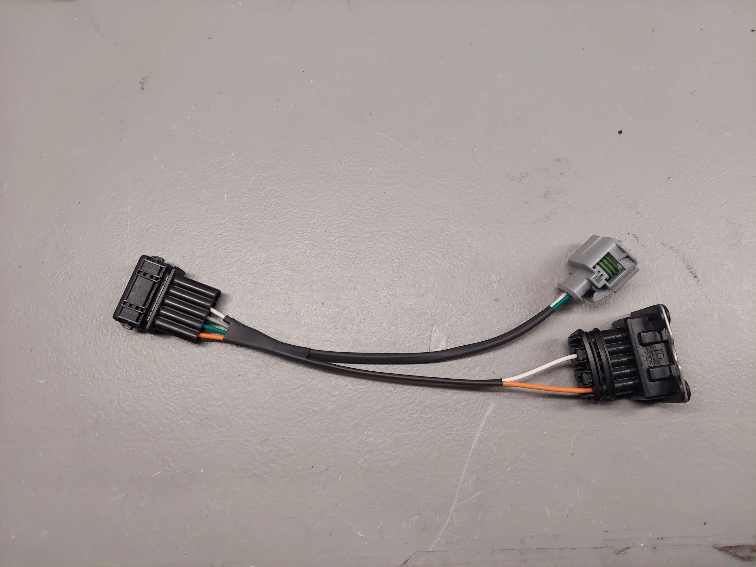
This is the adapter for the basic kit with afm delete. It has the iat sensor only
-
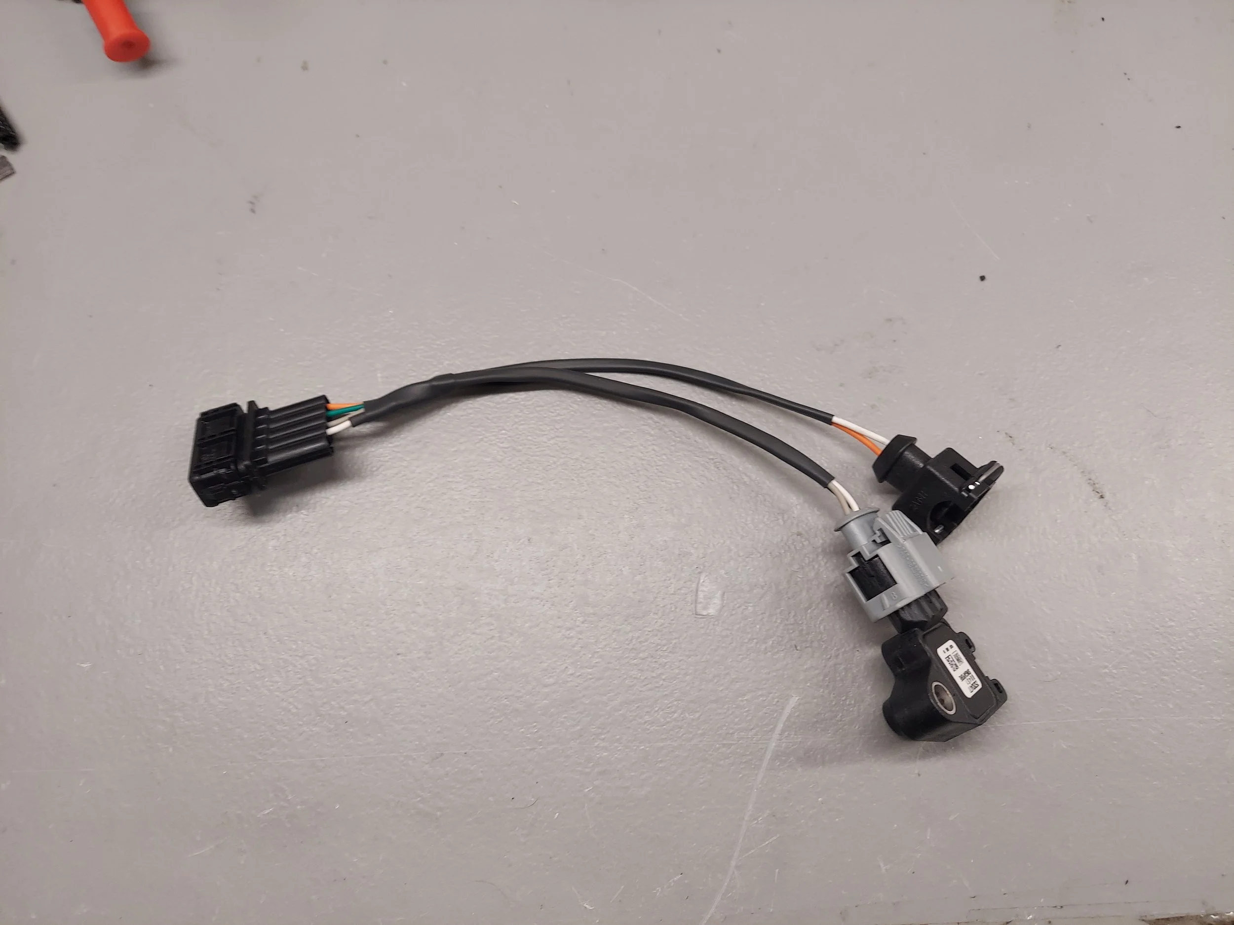
This is the adapter harness on the easy install kit for an afm delete. It has the external map sensor and Iat sensor
-
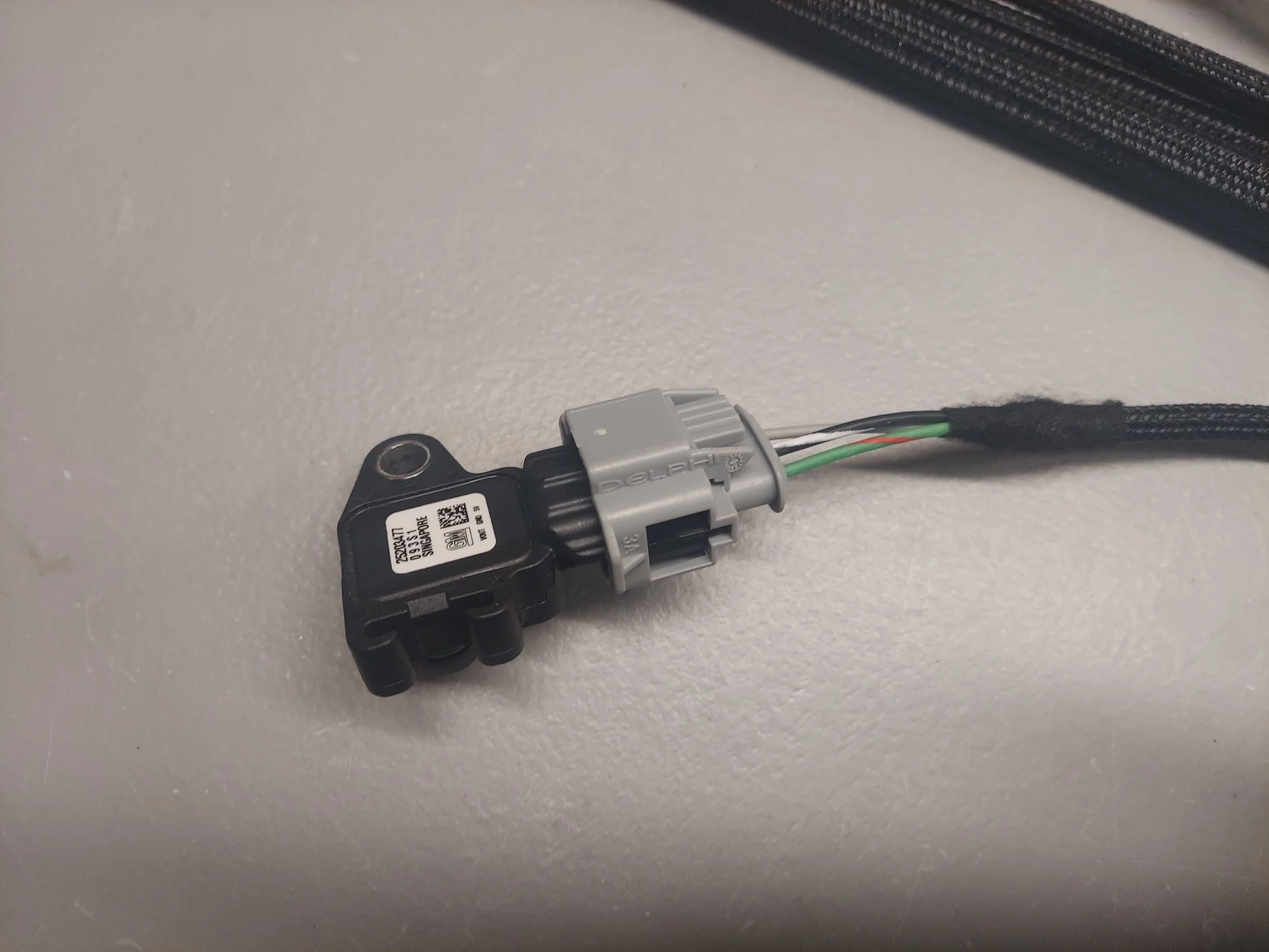
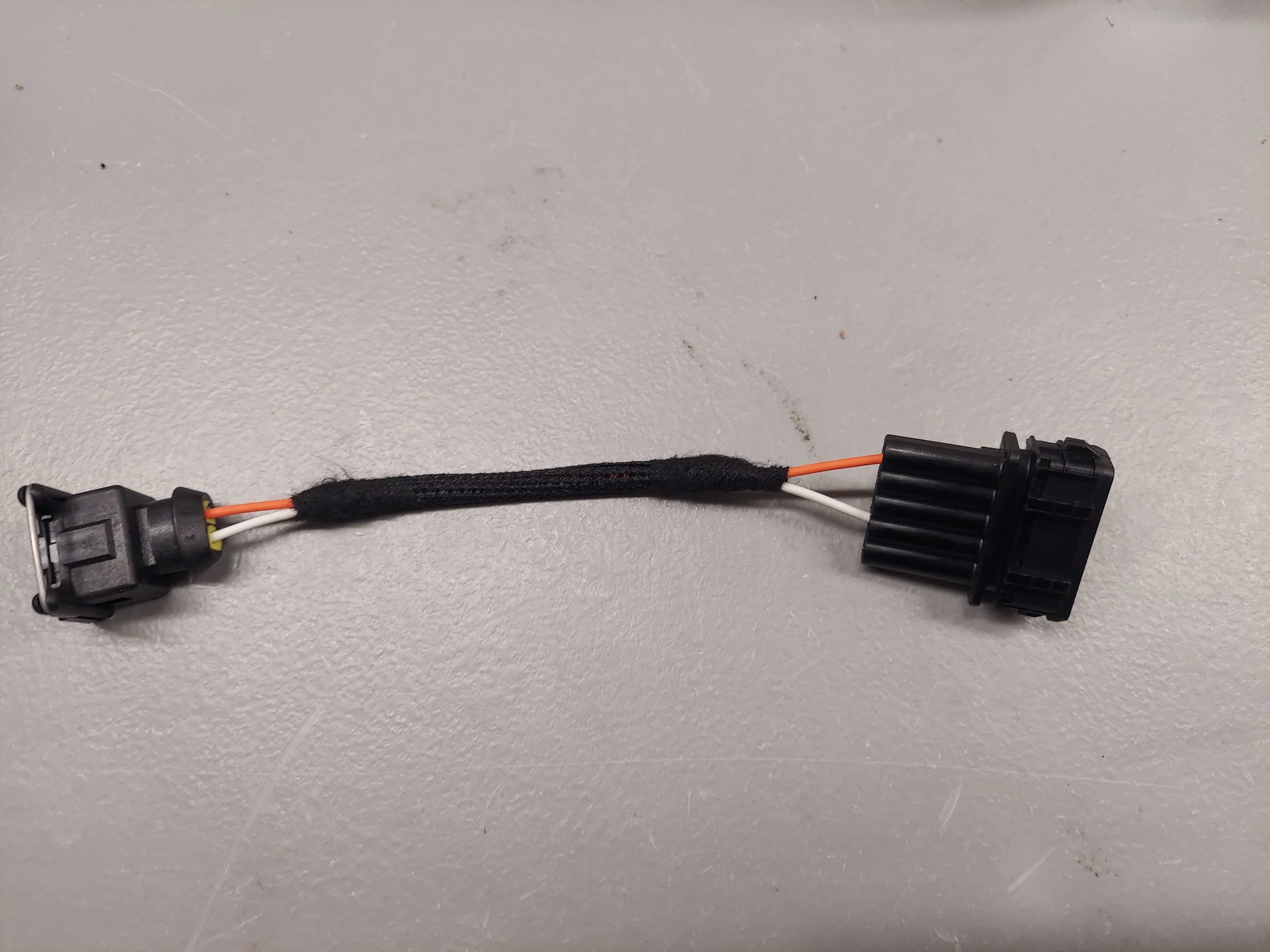
This is the adapter harness on the easy install kit for keeping the stock afm. It has the external map sensor only
-
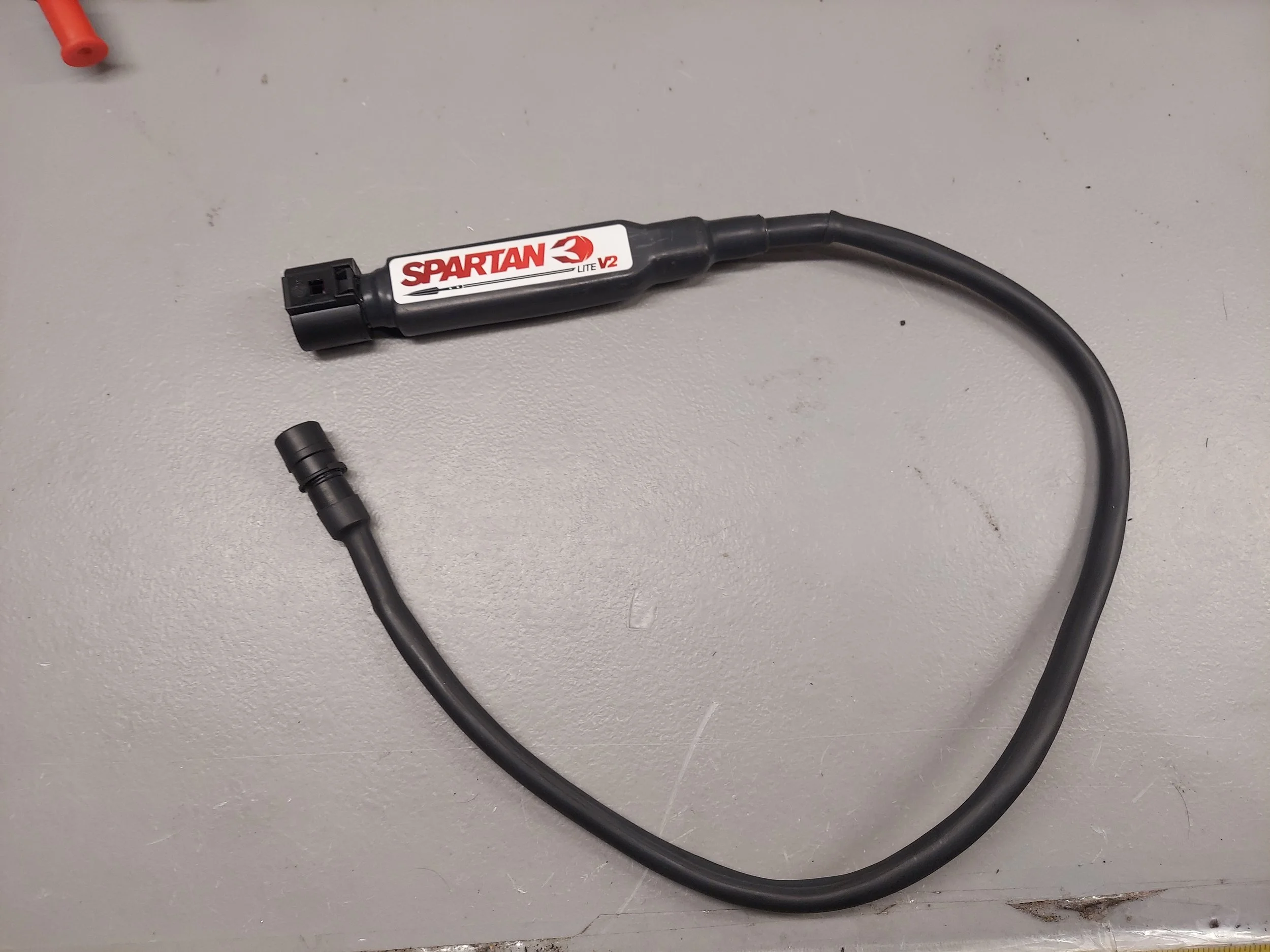
This is the shortened pnp wideband on the easy install kit. It plugs into your original o2 sensor plug
-

This is the wideband o2 sensor. This will replace the original o2 sensor. There will be two of these for dual wideband kits
-
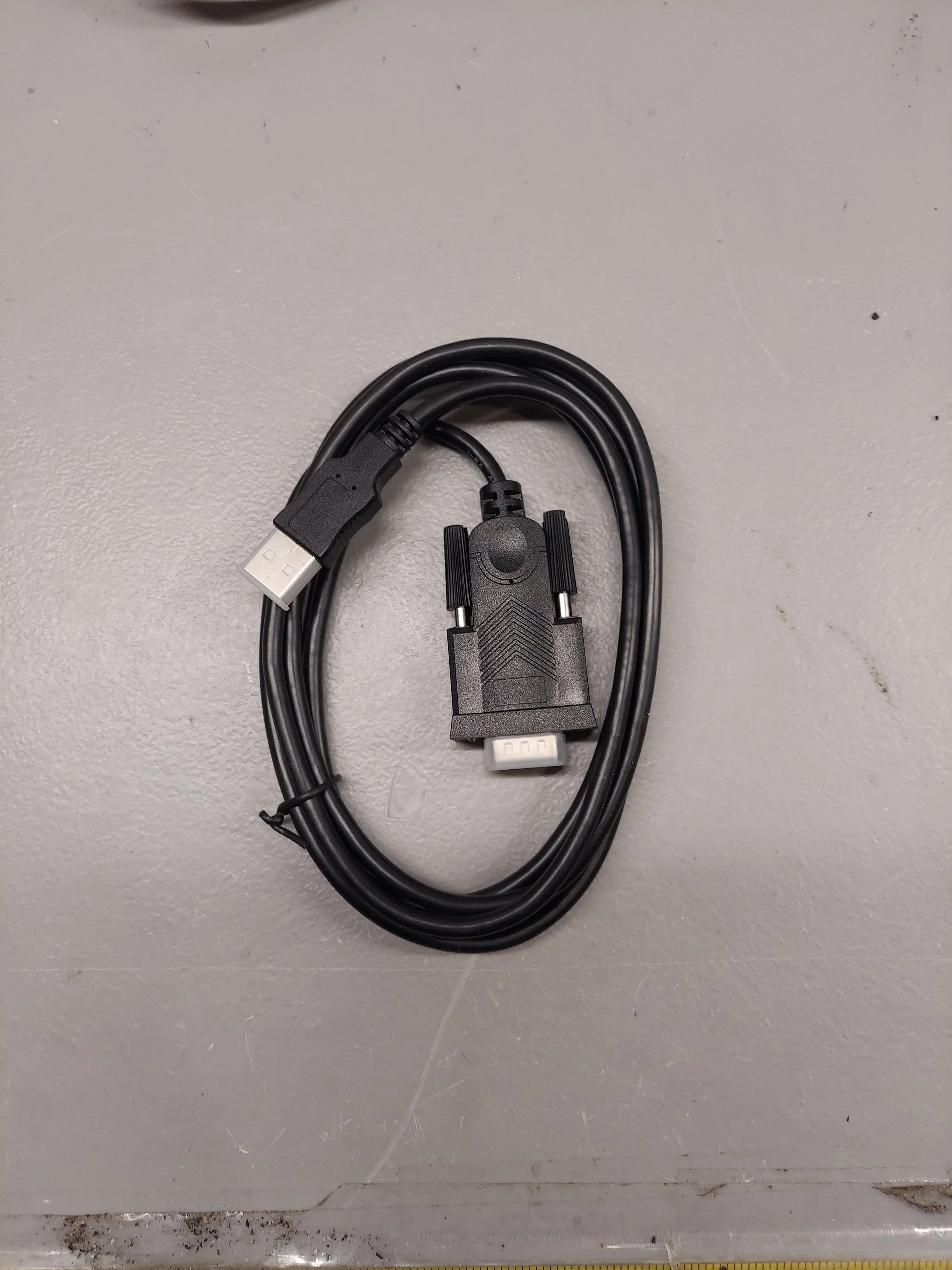
This is the data com cable. It will install on the back of the ecu
-
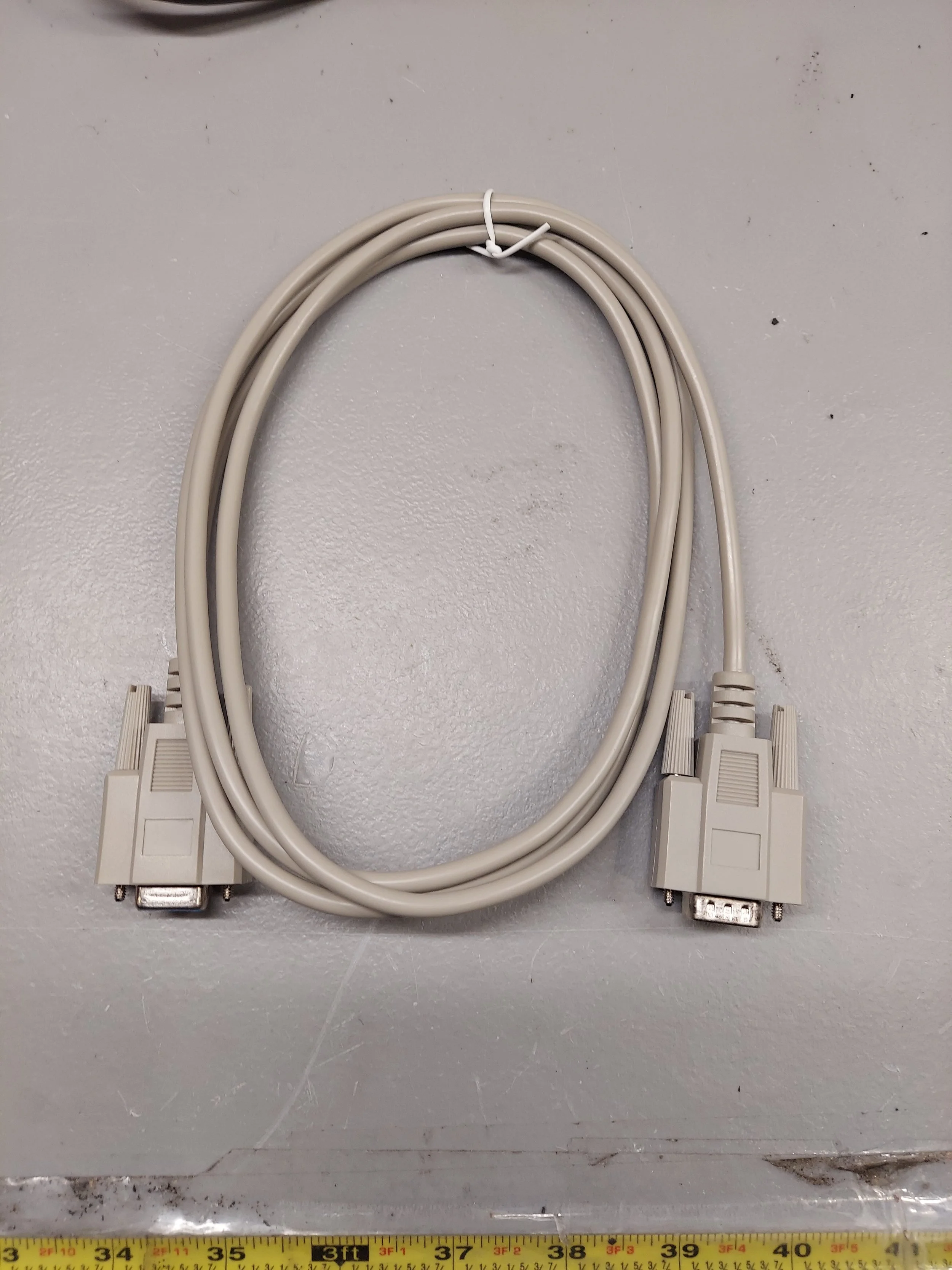
This is an extension harness for the data cable to the ecu. It is usually not needed
-
The 993 pnp ecu kit is fairly straight forward to install. If any other additional options (fuel psi, COP, DBW) are to be use, wiring will need to be run through the firewall to the ecu.
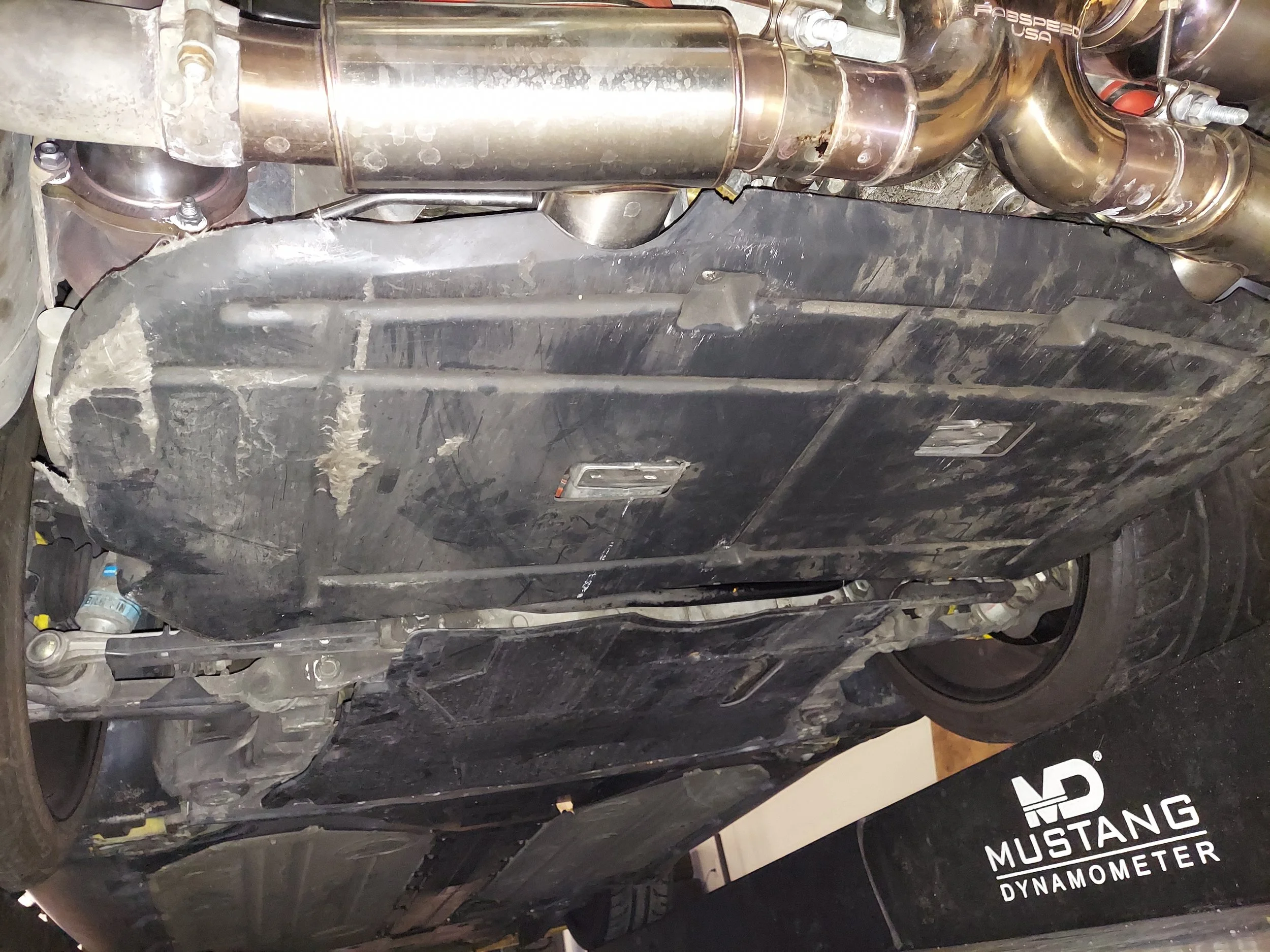
First step is to raise the rear of the vehicle on jack stands or drive on ramps to remove the splash shields
-
On turbo models it is best to remove the intercooler cover to make access easier. The are six screws that hold the cover down
-
b2/s1 black connector on passenger side
-
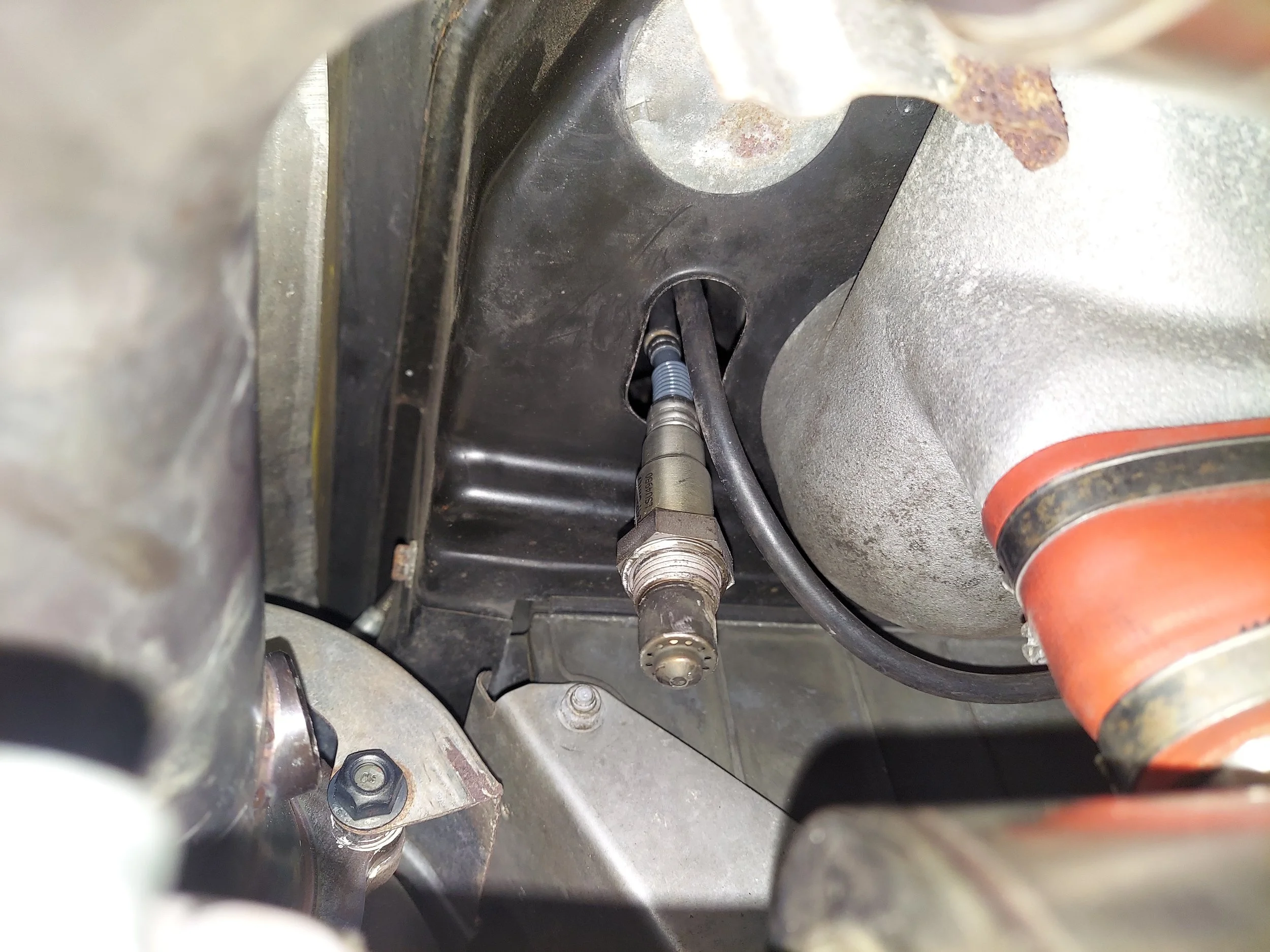
First up is probably the hardest part of the install, removing the old o2 sensors before the cats b1/s1 and b2/s1. Sensors can get seized over time so it maybe necessary to heat it up for removal. Do at your own risk.
The new o2 sensor will get run through the tin from the engine bay side down/out to the exhaust bung.
-
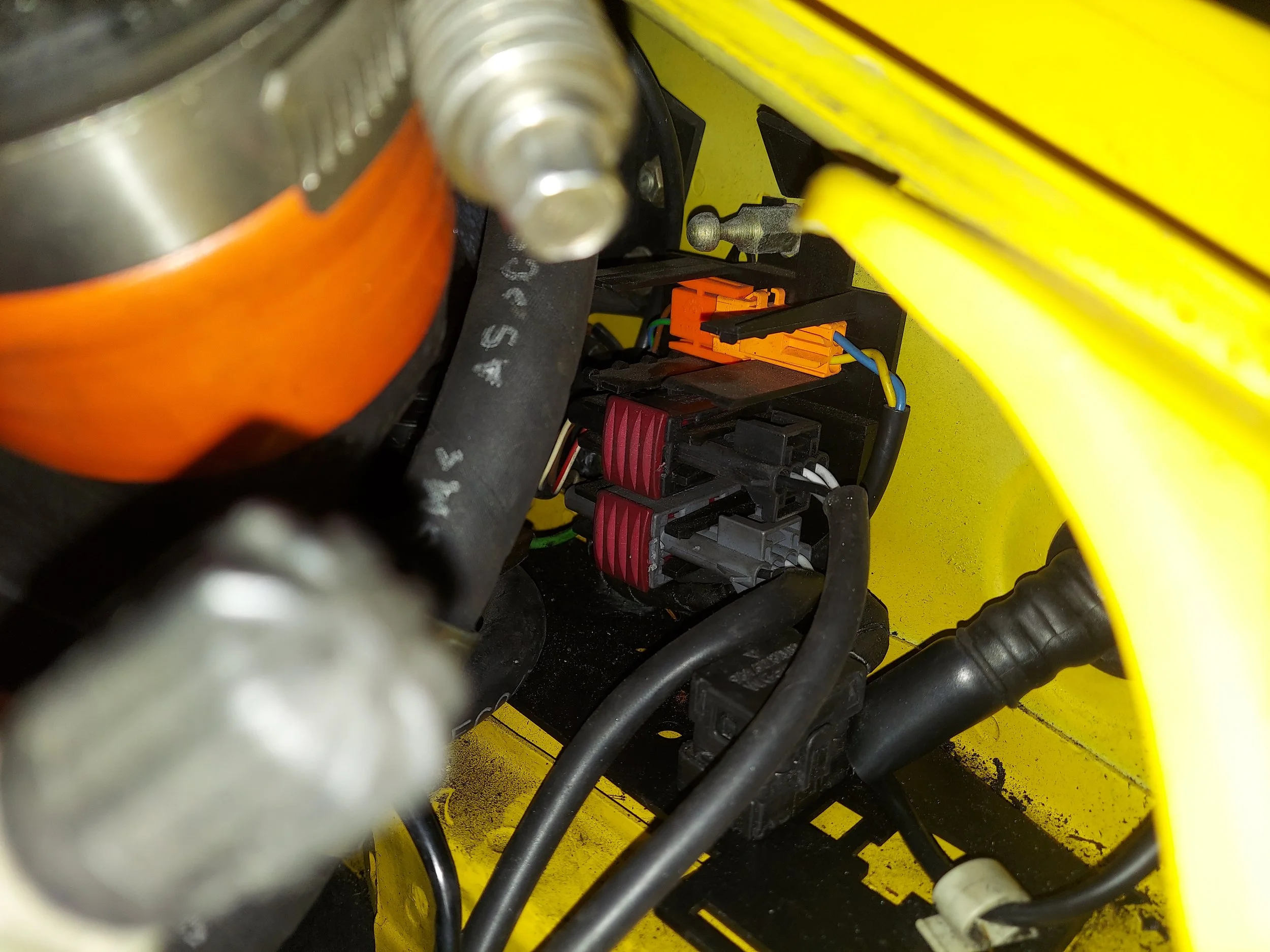
The wideband controller will get plugged into the original before cat b1/s1 and b2/s1 o2 sensor black 4 pin connector.
Above pic is of driver side connector
-
b2/s1 black connector on passenger side
-
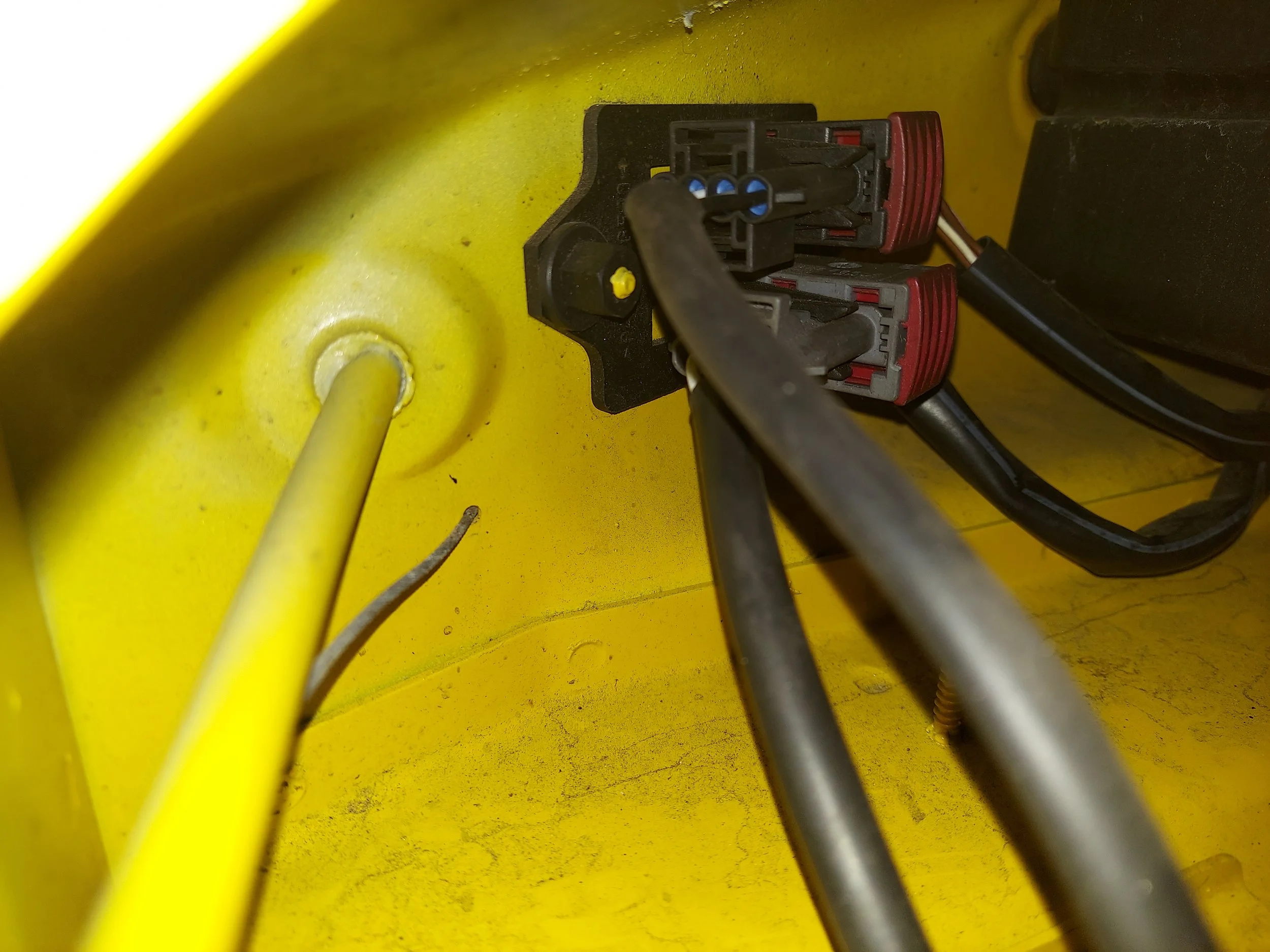
Wideband controller tuck away by the chassis connectors on drivers side. Some o2 sensors have shorter wire lengths which will not allow the controller to be tucked
-
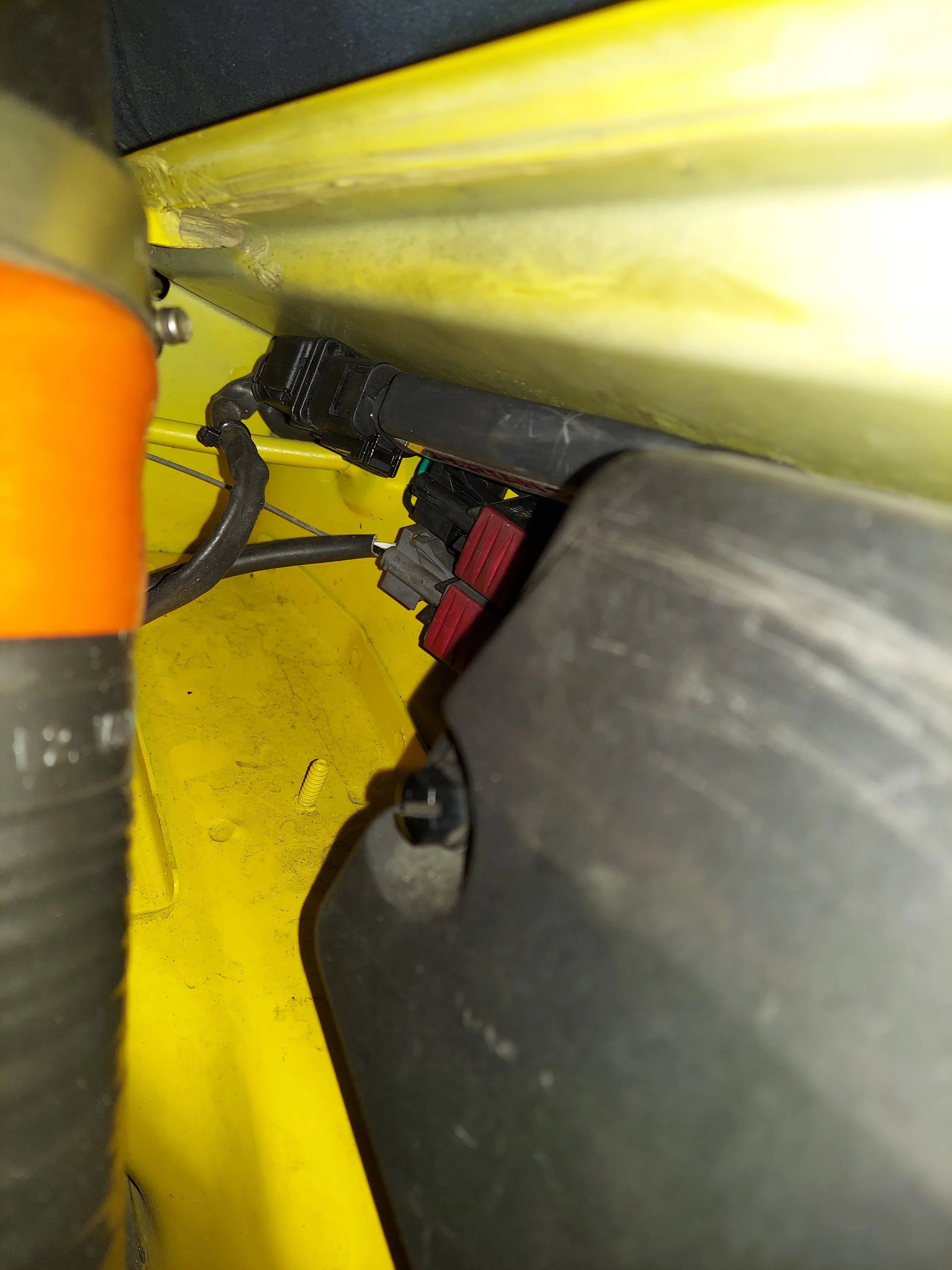
b2/s1 passenger side widebnad controller tucked
-
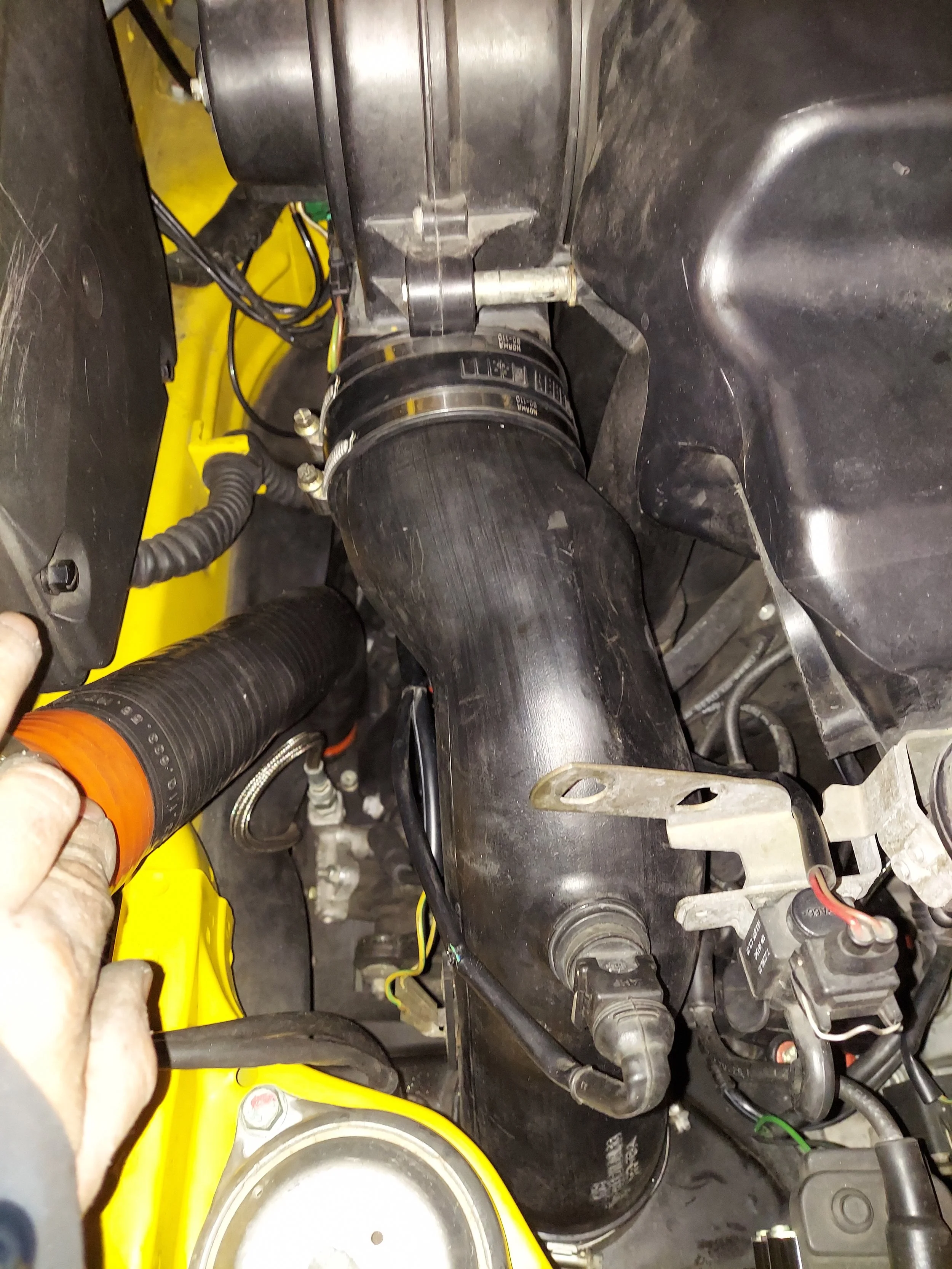
On turbo models removing the intercooler to help gain access to the crank trigger plug makes life easier. There are 3 allen bolts to the throttle body and 2 allen bolts by the fan shroud.
Remember to unplug the iat sensor
-
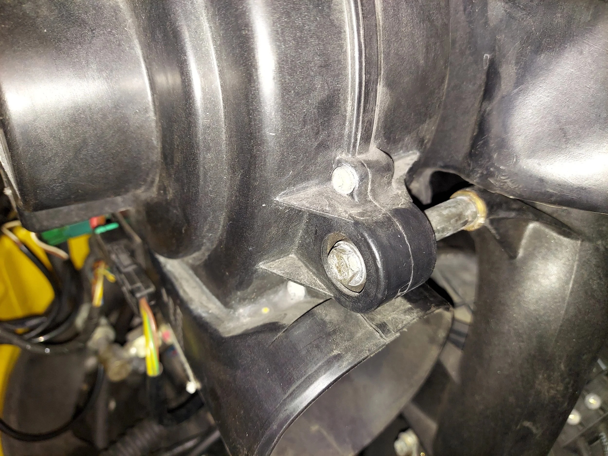
Lower intercooler allen bolts. These use a square nut on the back. Make sure you have your hand on the nut when removing the bolts or the nut will fall and likely get lost in the engine bay
-
Square nut on the back side of lower intercooler allen bolts
-
This adapter is for the basic kit with afm removed. The kit will come with an iat with or without threads.
The iat without threads can use a simple grommet to mount in your afm delete tube.
The iat with threads has m12×1.5 threads. You can drill/tap your afm delete tube to mount
-
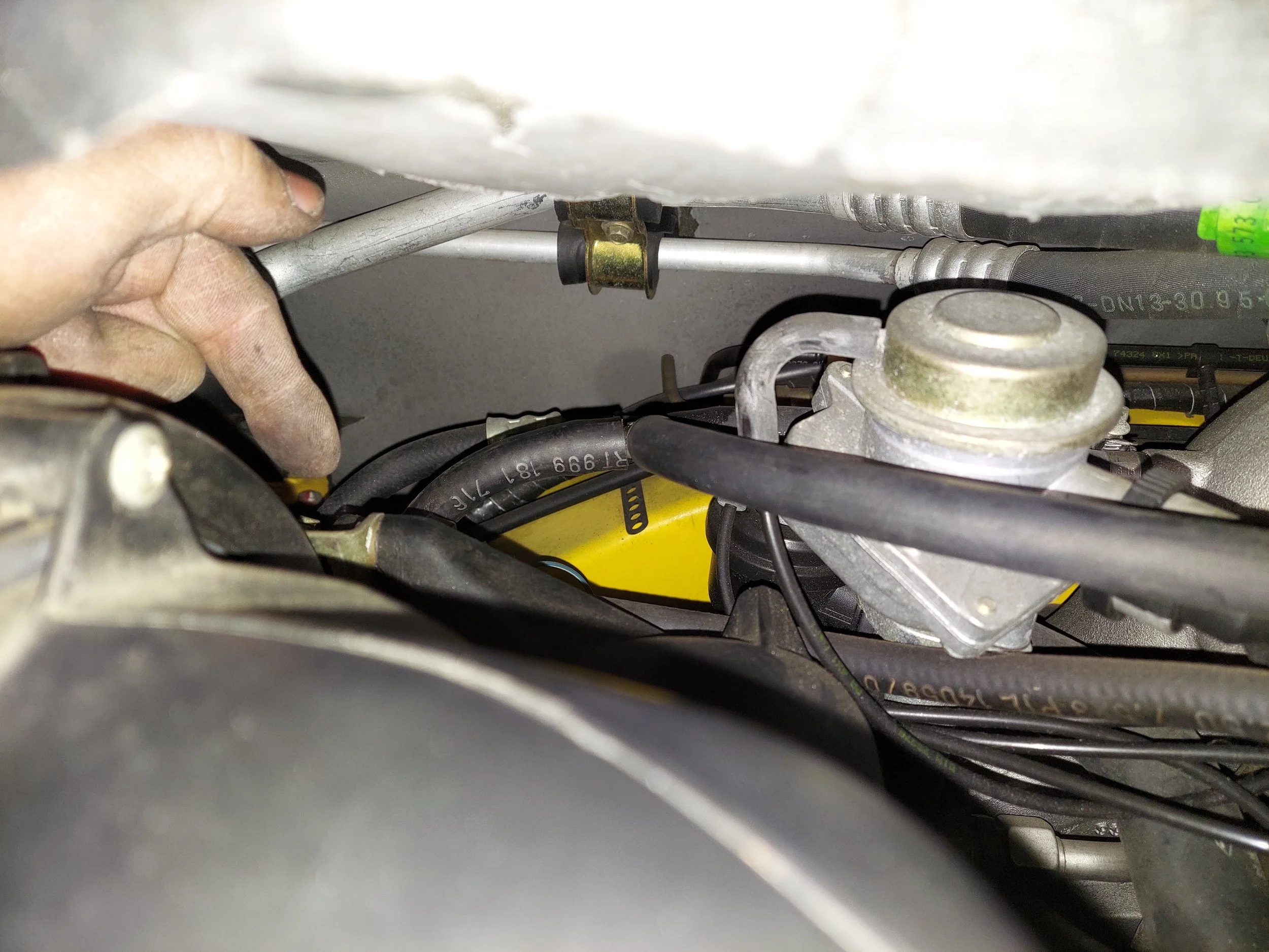
Next step is not neccesary, but makes life easier to replace the crank trigger and its connector.
Remove the blower motor shroud, tueb and blower motor.
Also On turbo models if your upgrading injectors this needs to be done.
-
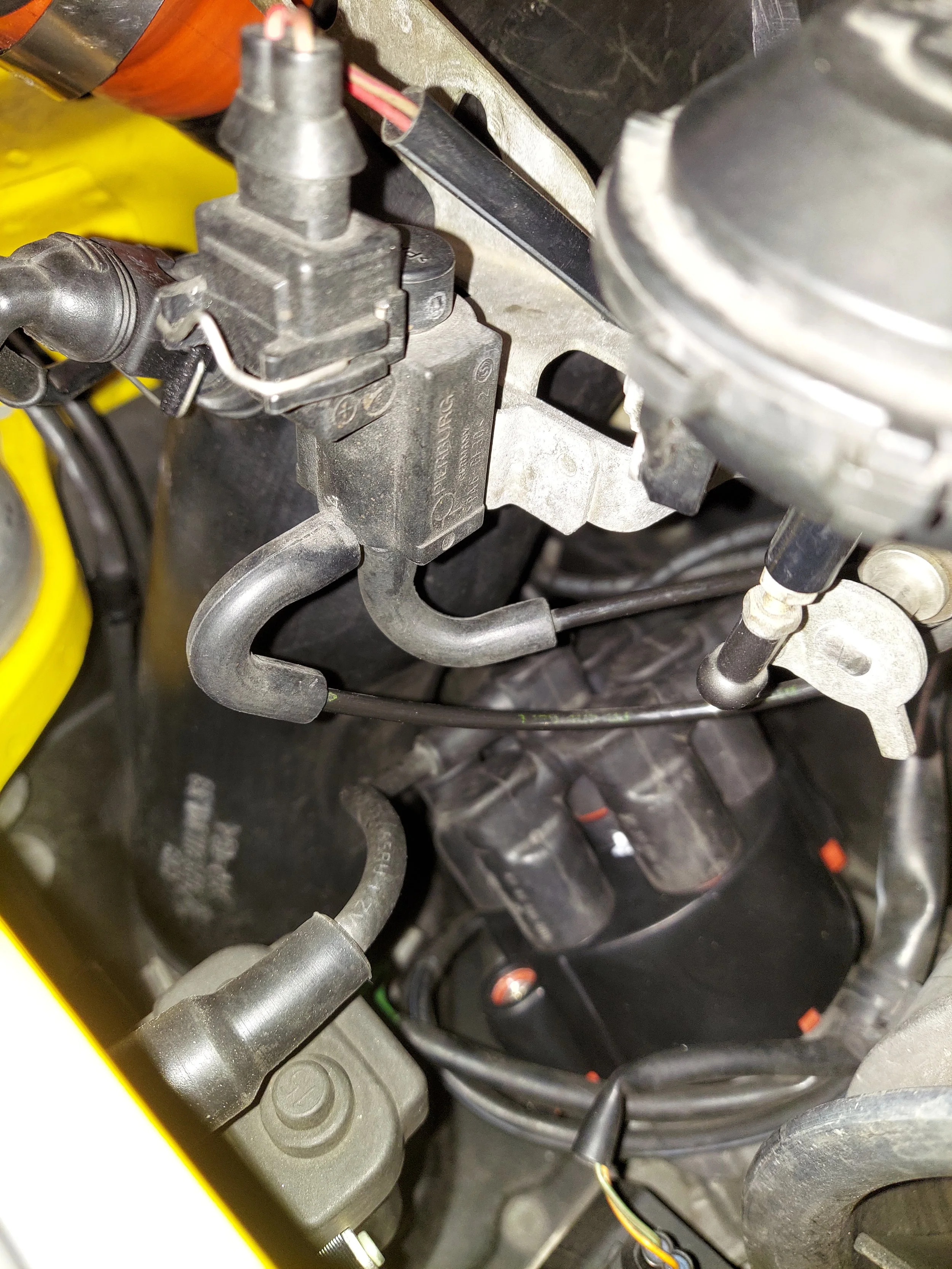
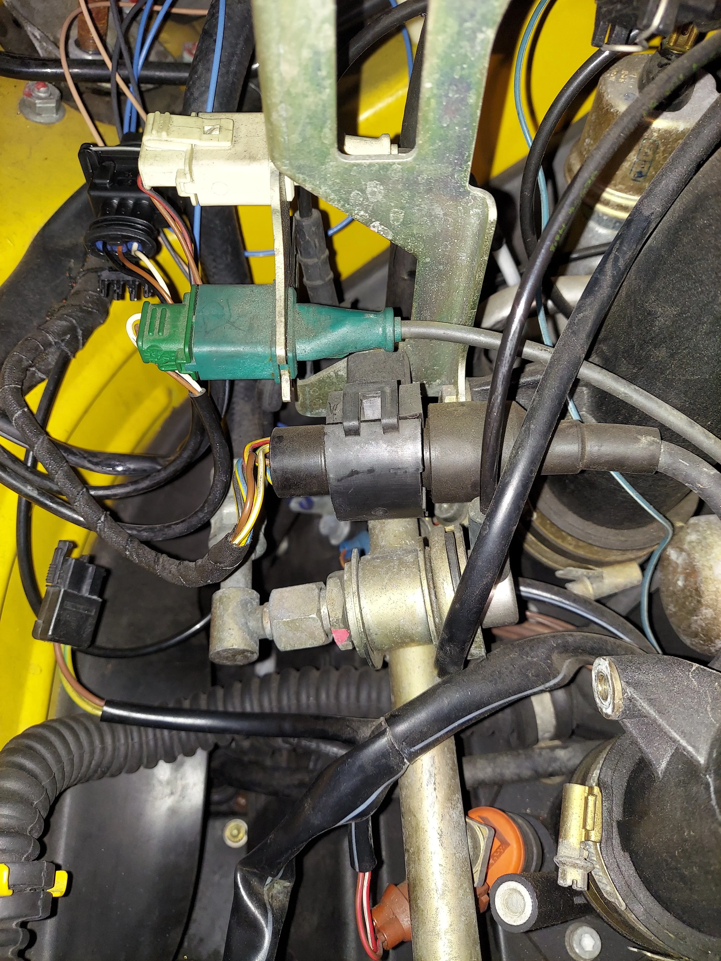
You’ll need to unplug the solenoid and vac hose for the blower vent valve
-
There are 3 bolts holding the blower motor on
-
Hidden lower bolt on blower motor
-
Hidden upper bolt on top rear of the blower motor
-
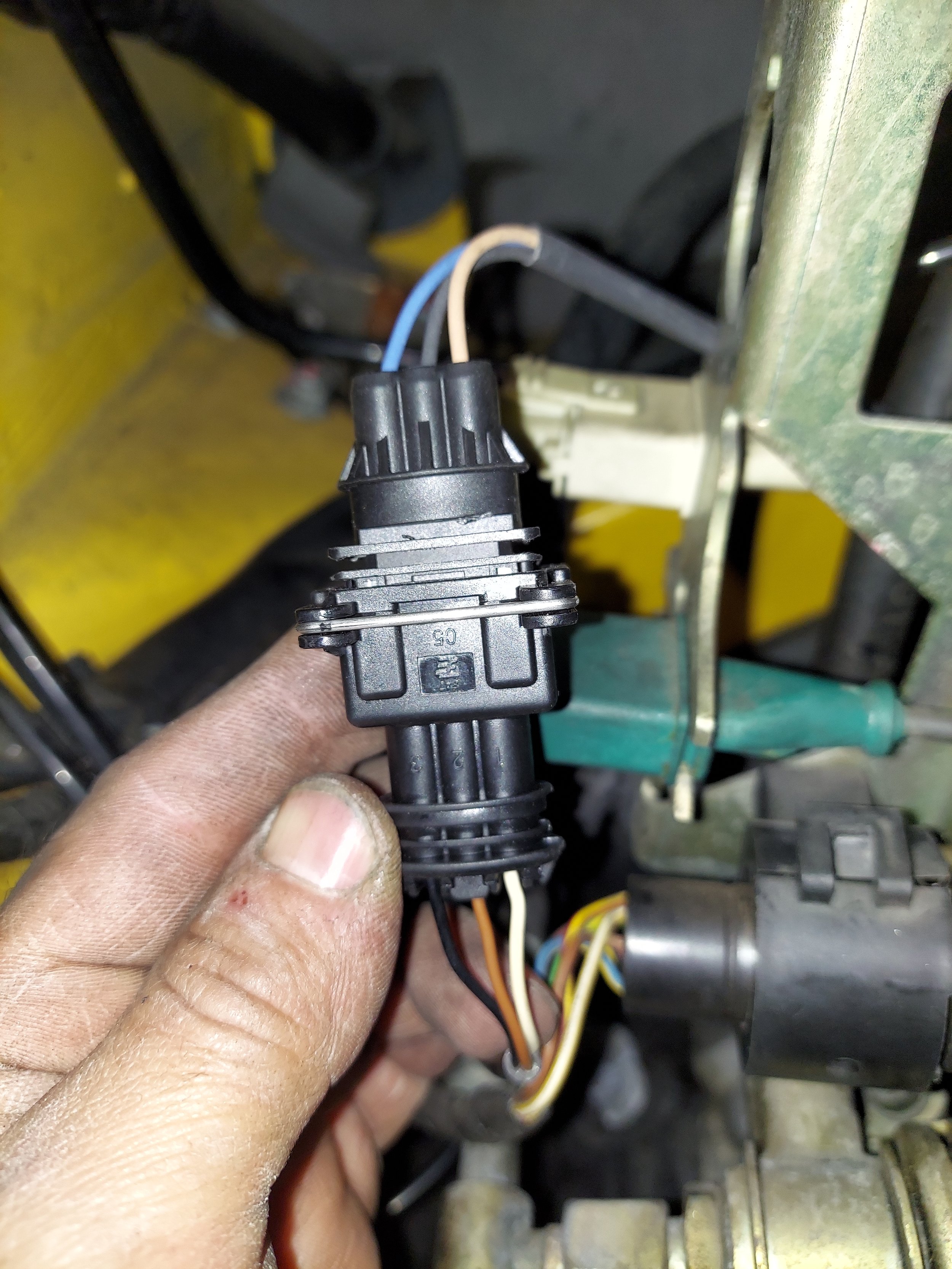
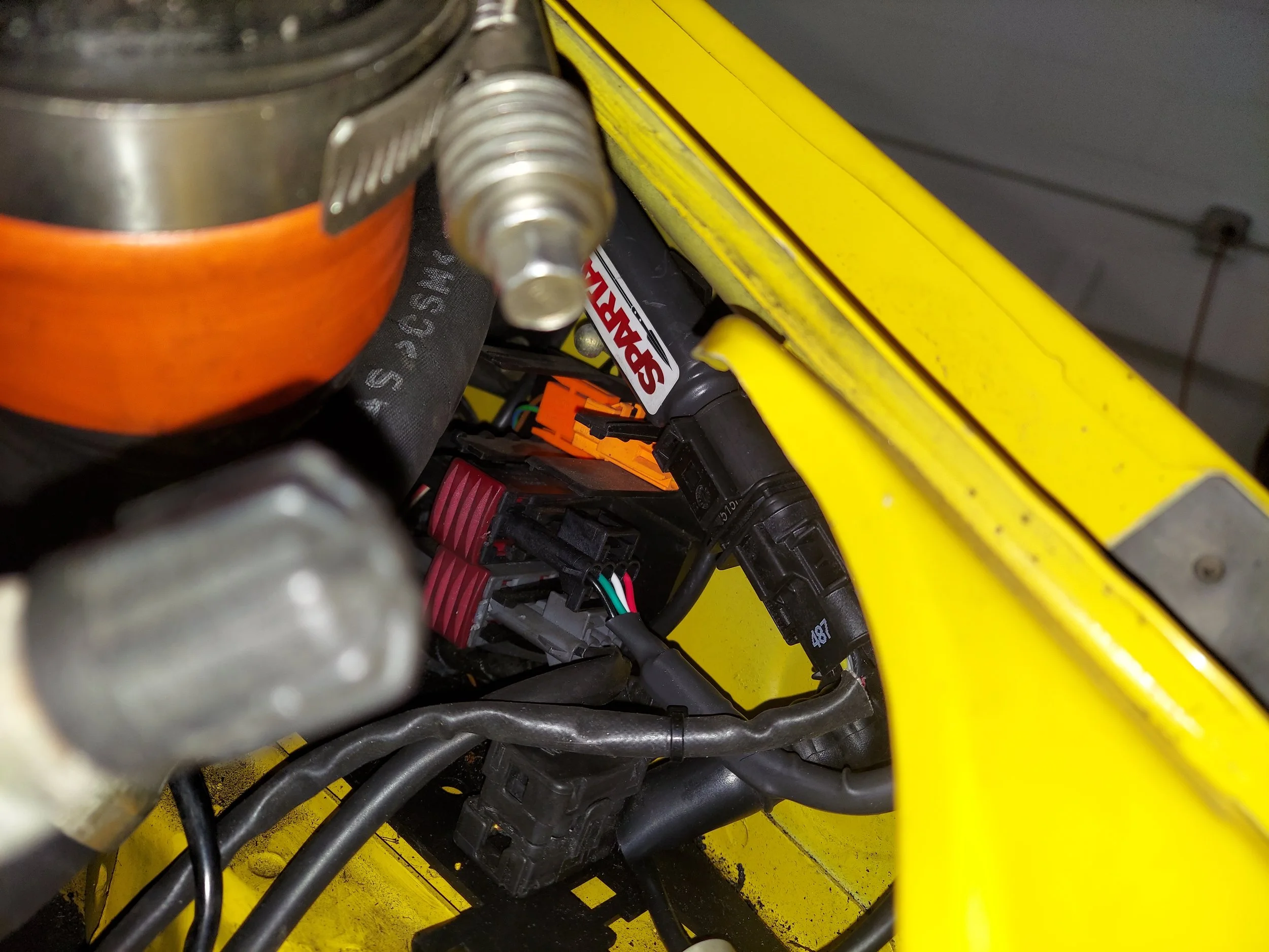
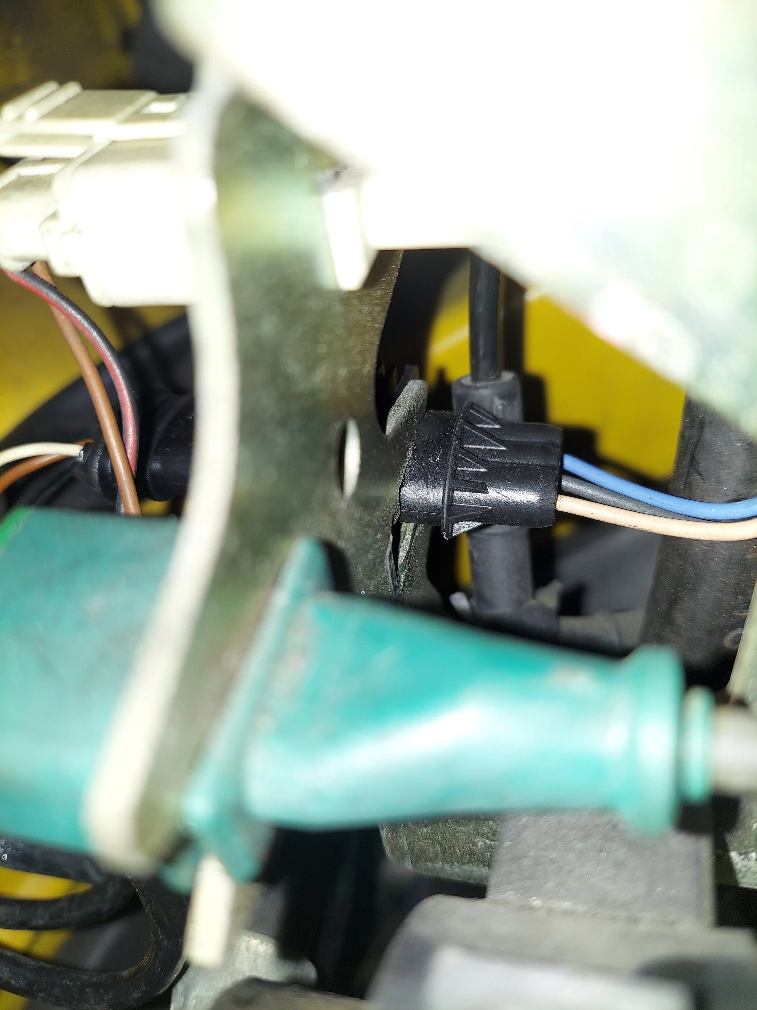
The black crank sensor connector will need to be depinned and switched out for the new hall sensor connector. The pin orientation on the original connector will be the same.
Pin 1 - white wire, this line up with the tan wire on the hall sensor
Pin 2 - brown wire, this lines up with the black wire on the hall sensor
Pin 3 - black wire, this lines up with the blue wire on the hall sensor
-
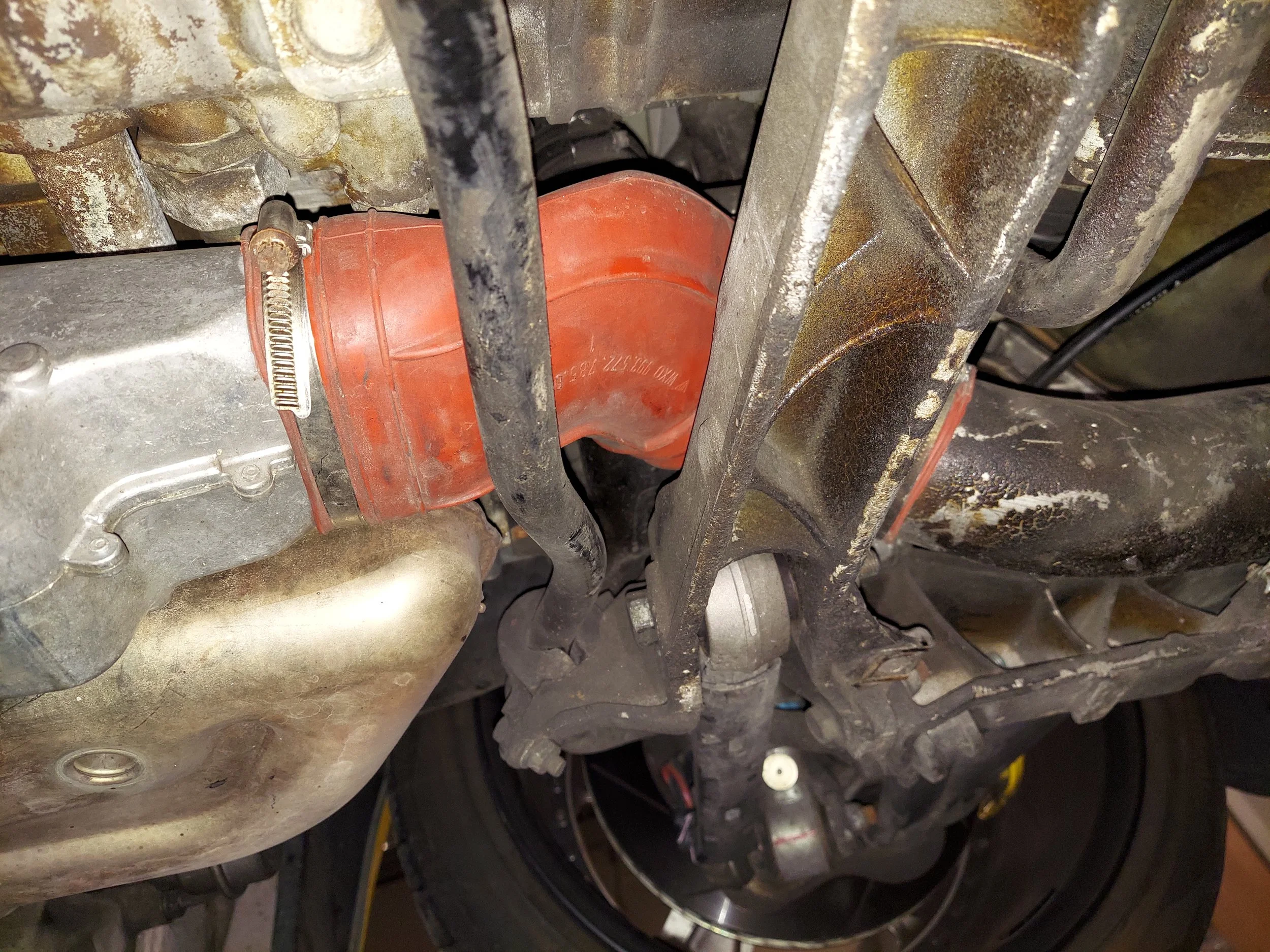
Next is to move under the car to replace the crank sensor. Removing the driver side heat duct makes this much easier. Remove the orange heat duct
-
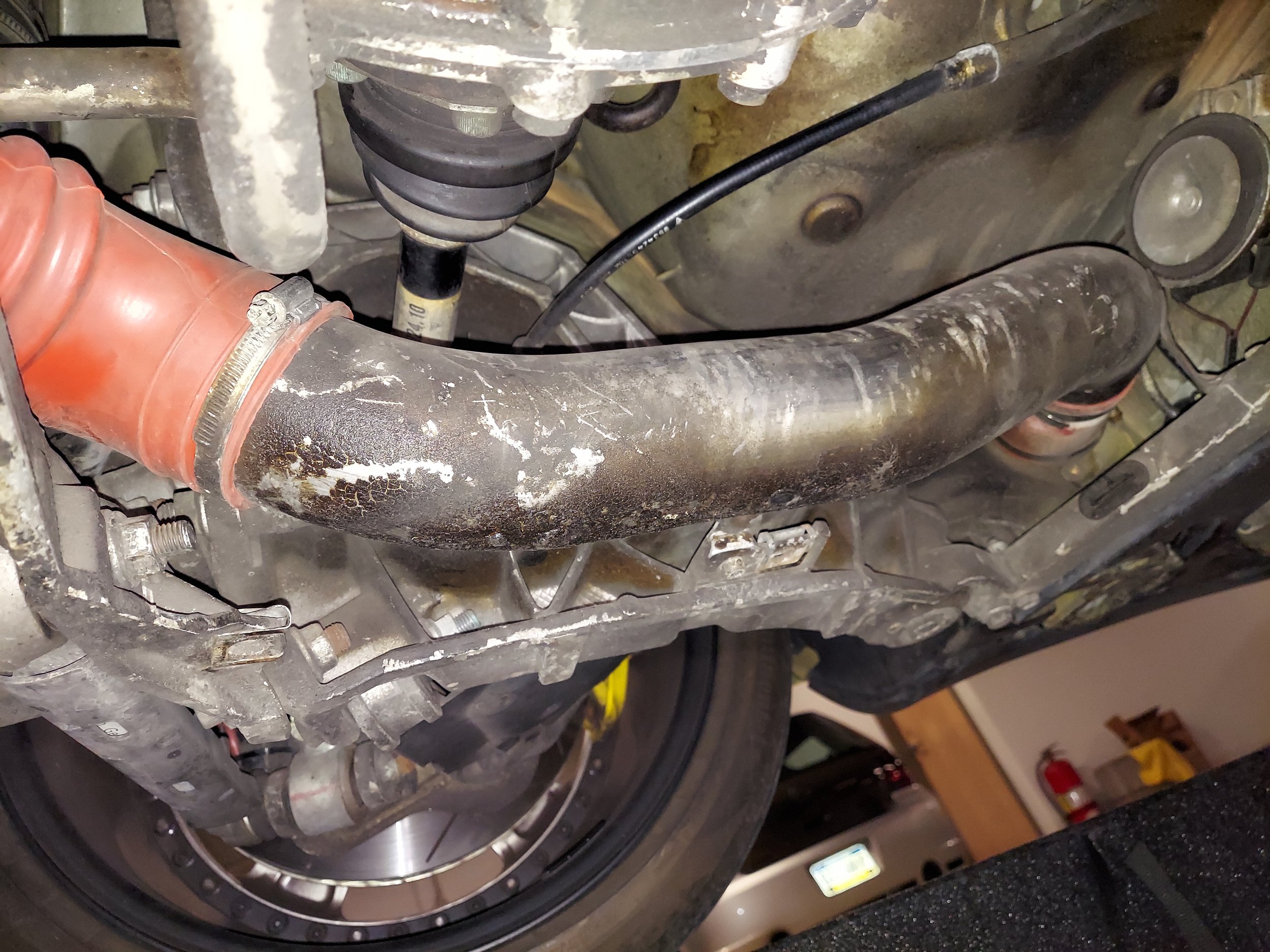
Remove the aluminum heat duct tube. There are two bolts that hold this down
-
Remove the air duct on the side of the transmission
-
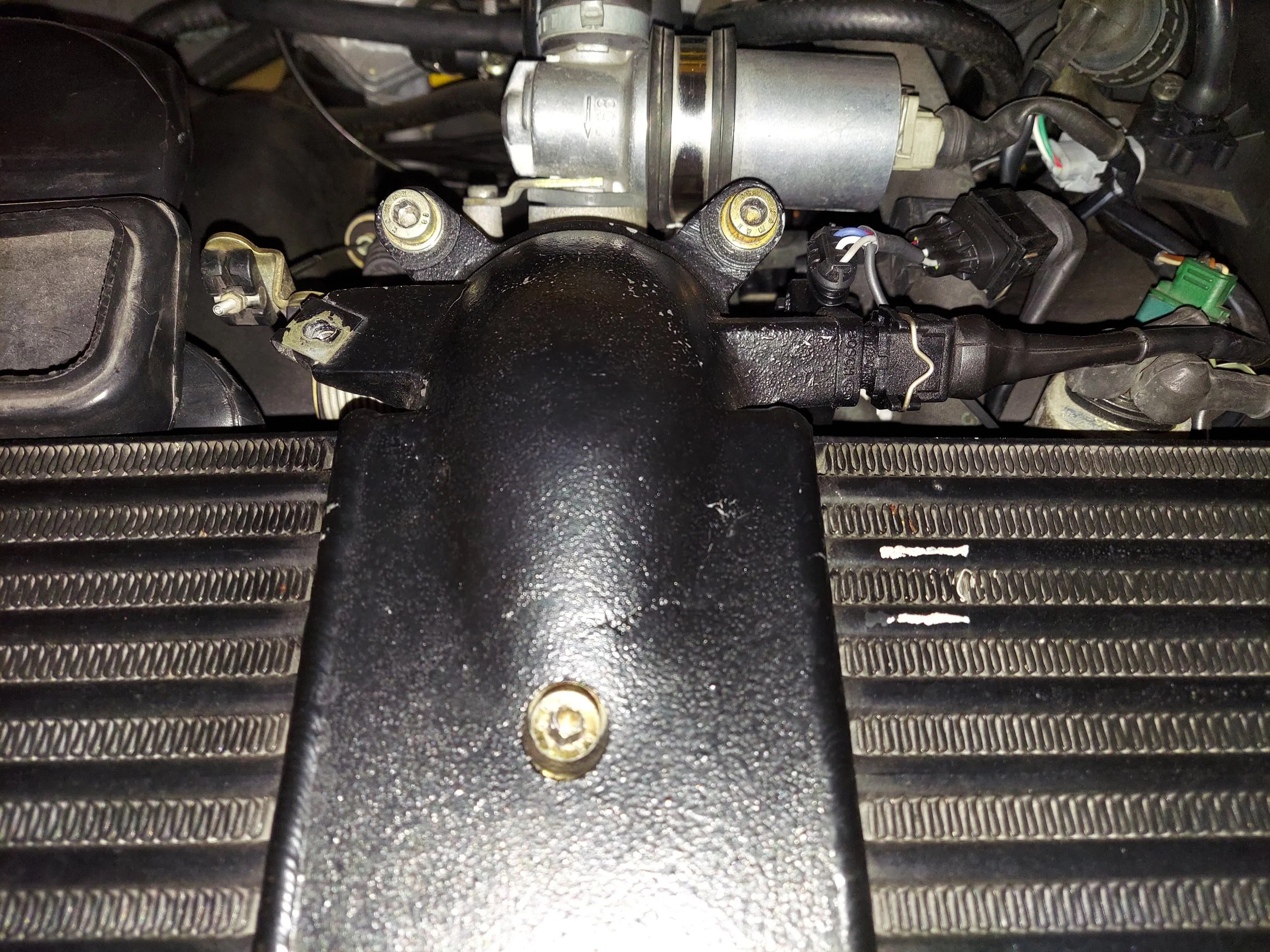
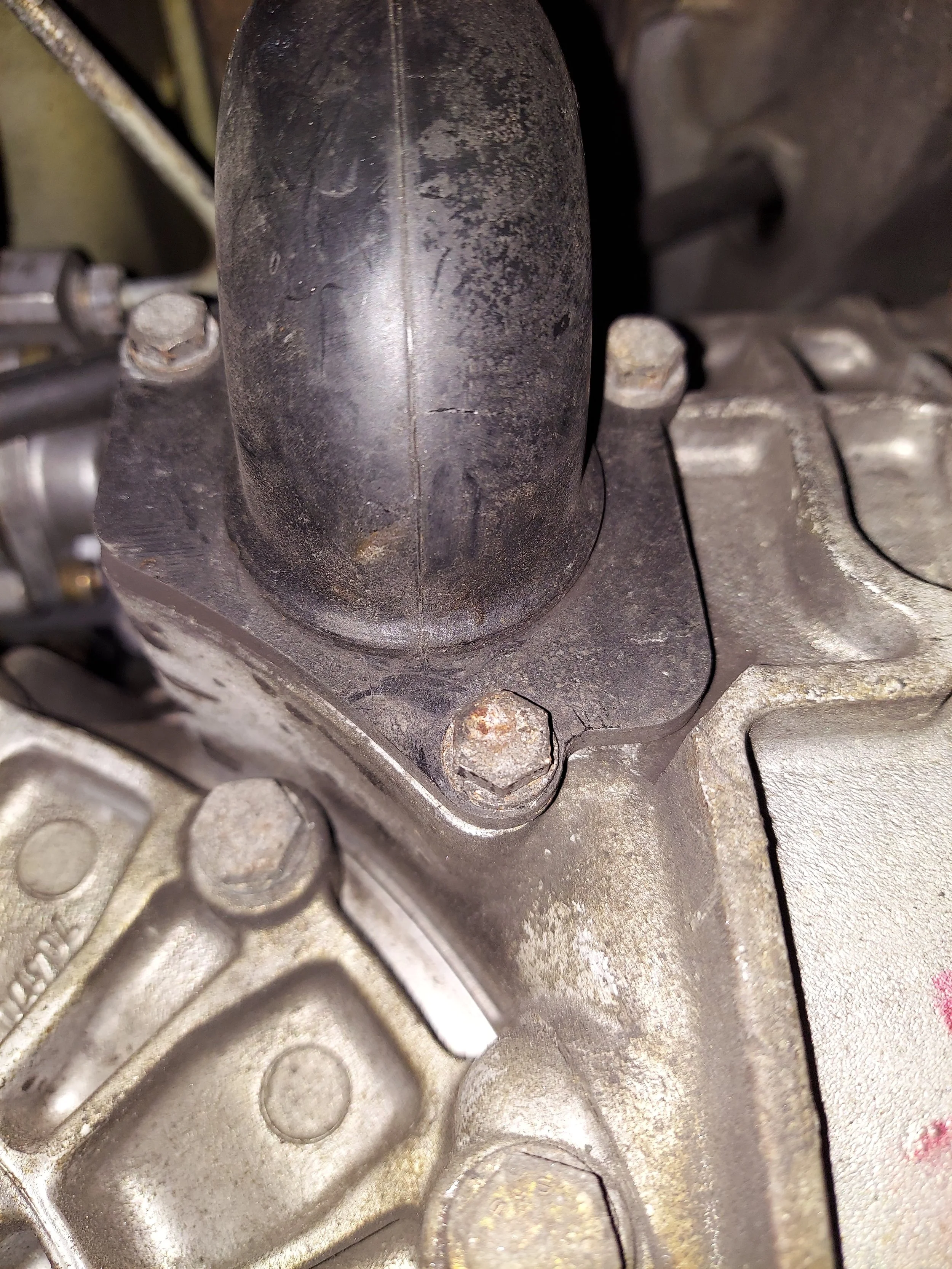
Remove the crank sensor bracket to install the new hall sensor
-

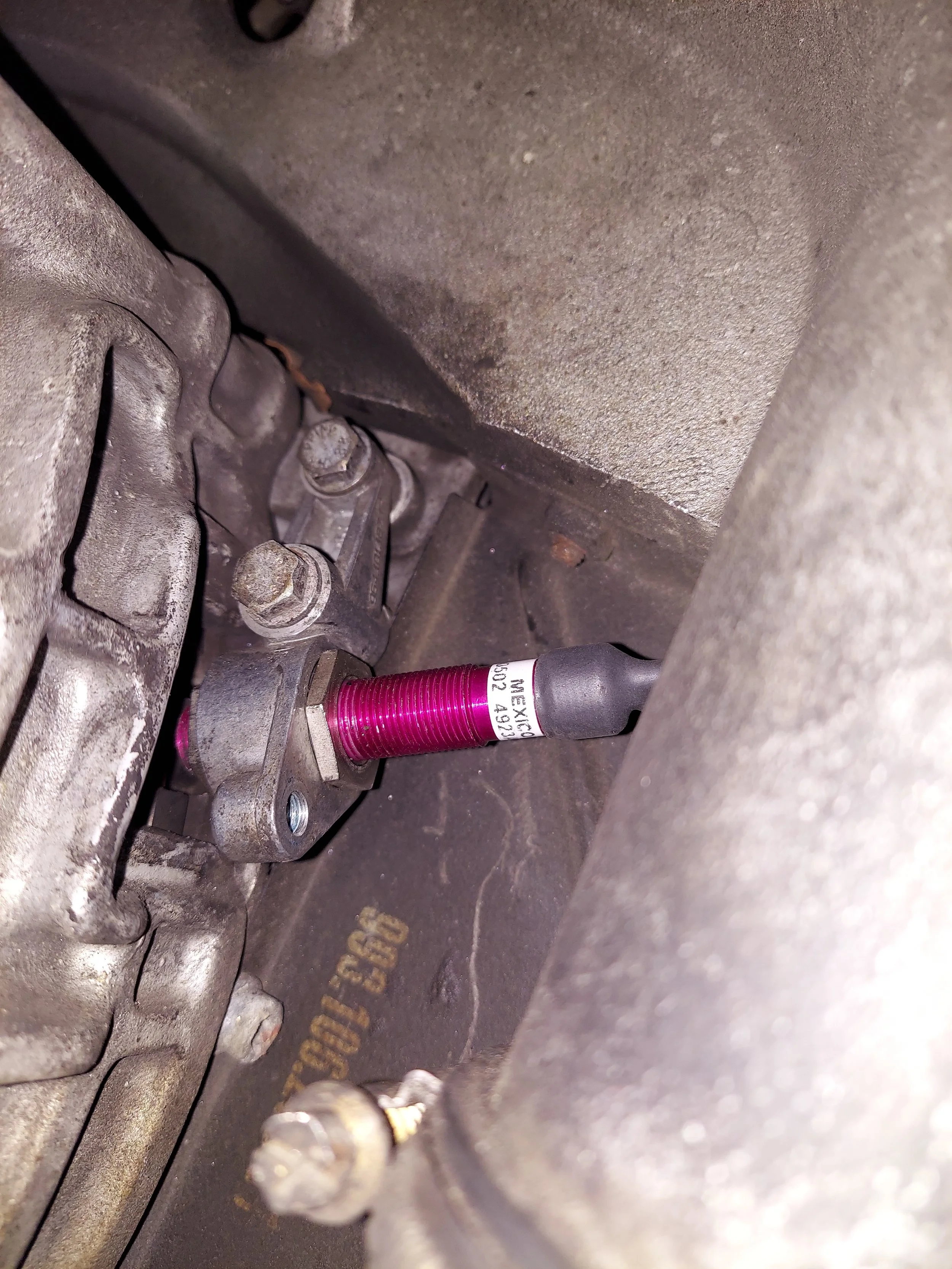
Install the new hall sensor and centering bushing in the crank sensor bracket. I have blue locktite the upper nut to set the adjustment. The lower nut should be locktite and tightend
-
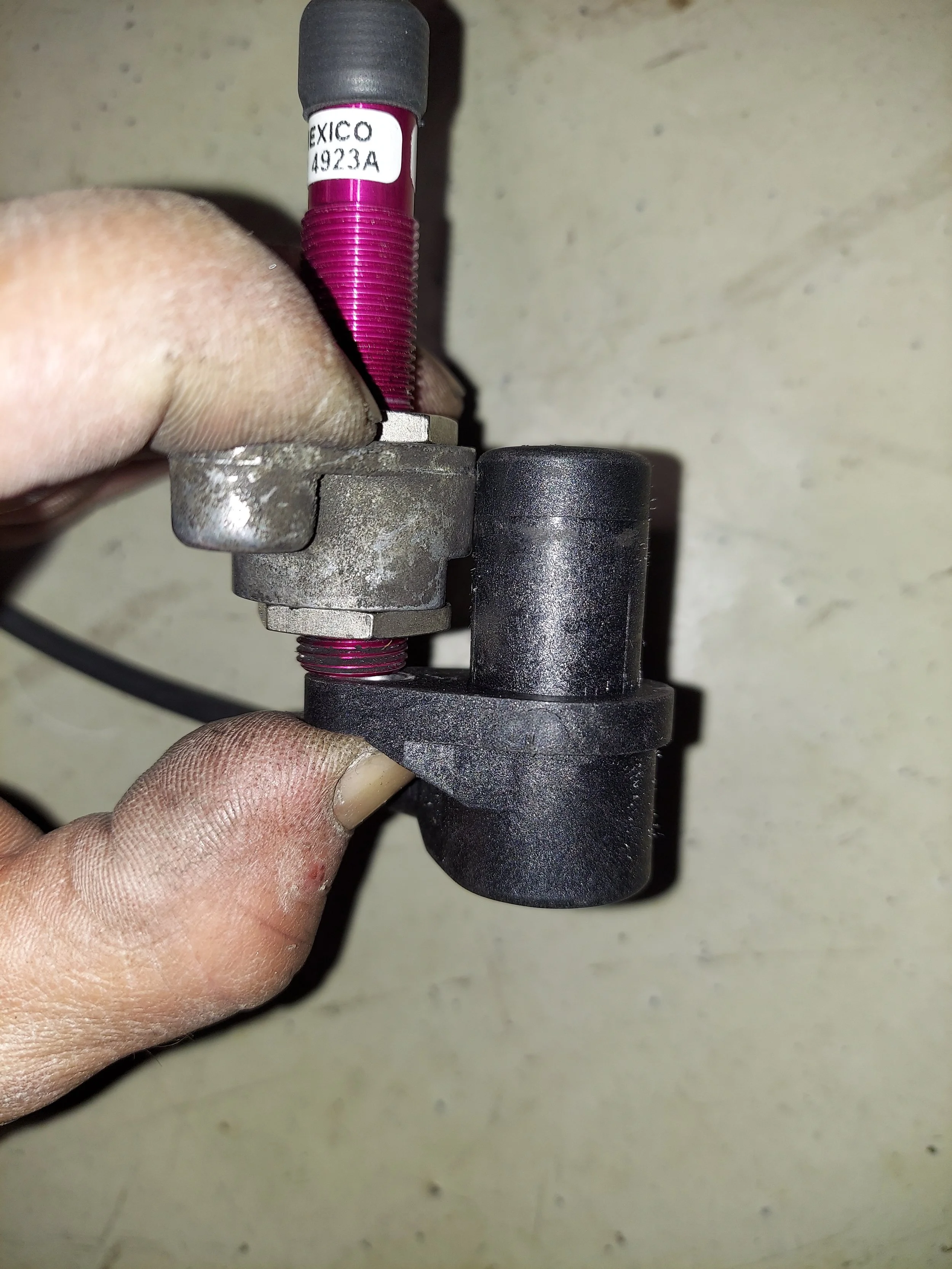
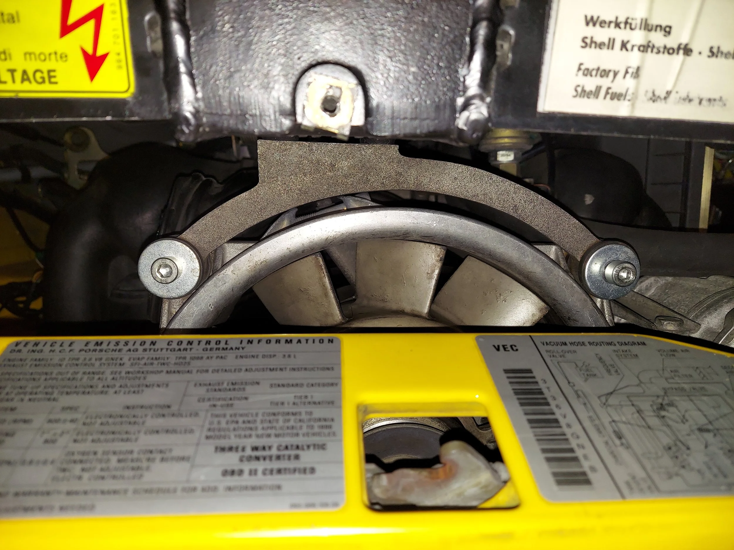
Check for reference that the old crank senor lines up flush with the top of the crank trigger bracket by holding its mounting tab on the bottom of the new hall sensor. This will help verify that the adjustment is correct
-
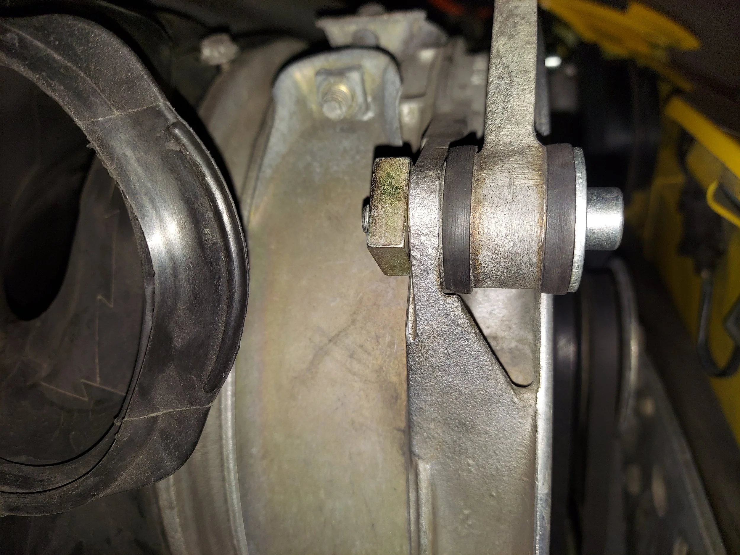
Install the crank sensor bracket with the the new hall sensor. Make sure the bracket is adjust so the hall sensors isn’t hitting the flywheel trigger.
-
Clip the new hall sensor into the bracket
-
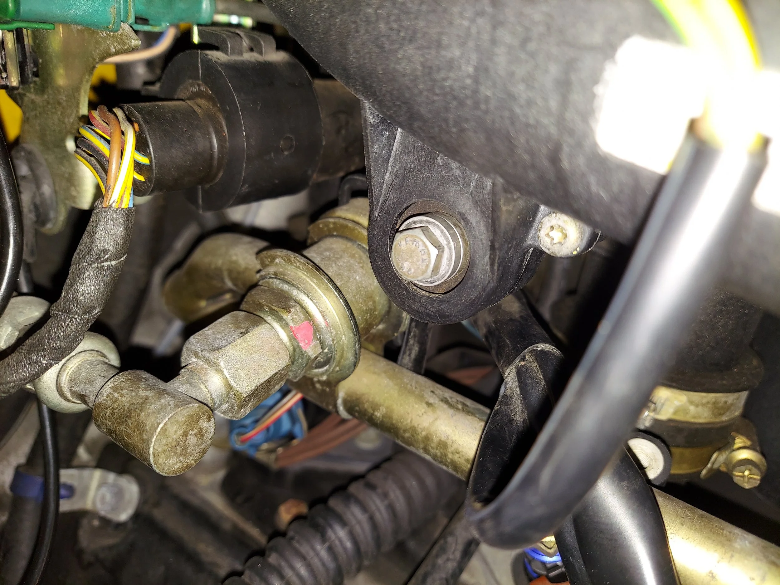
If installing injectors remove the round connector holder above the fuel pressure regulator
-
Unbolt the allens that hold the rail down to replace the injectors. Lube the new injectors orings with a grease or oil to help the install easier
-
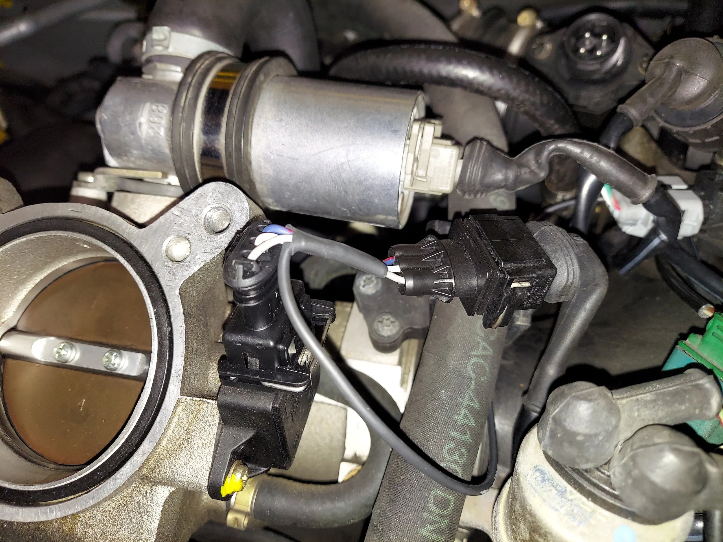
Plug tps adapter harness into tps sensor
-
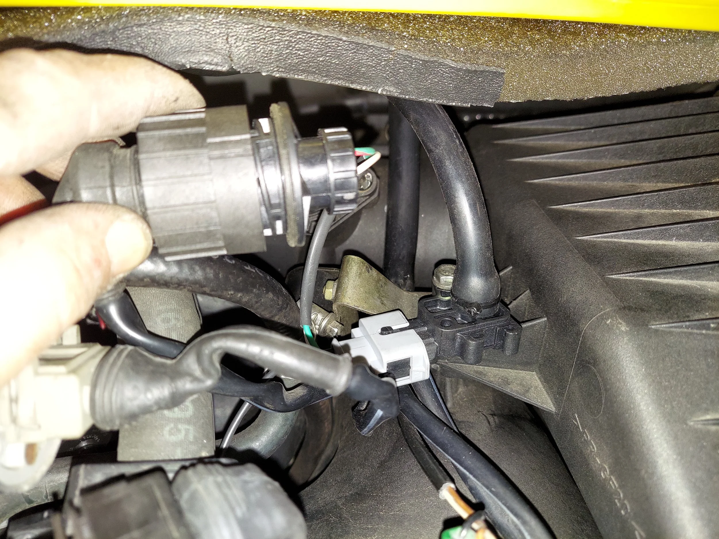
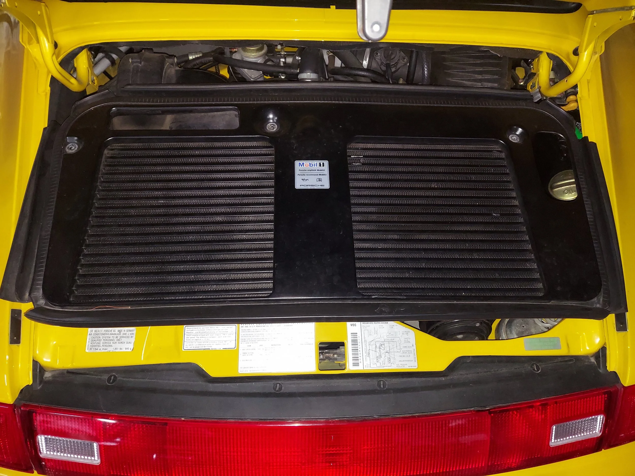
Unplug the maf sensor and plug its connector into the adapter harness. You can also remove the top air box bolt to mount the new map sensor.
-
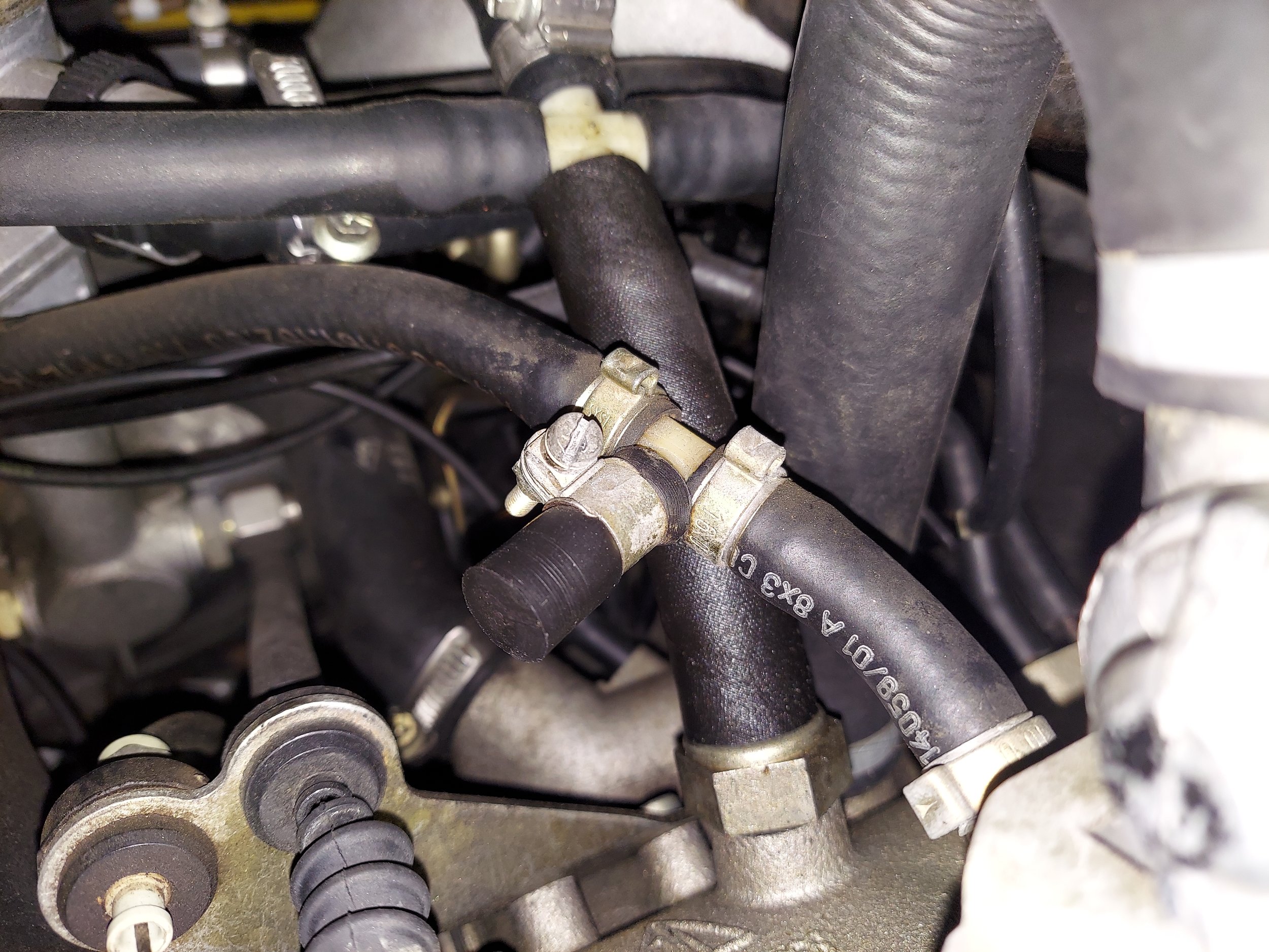
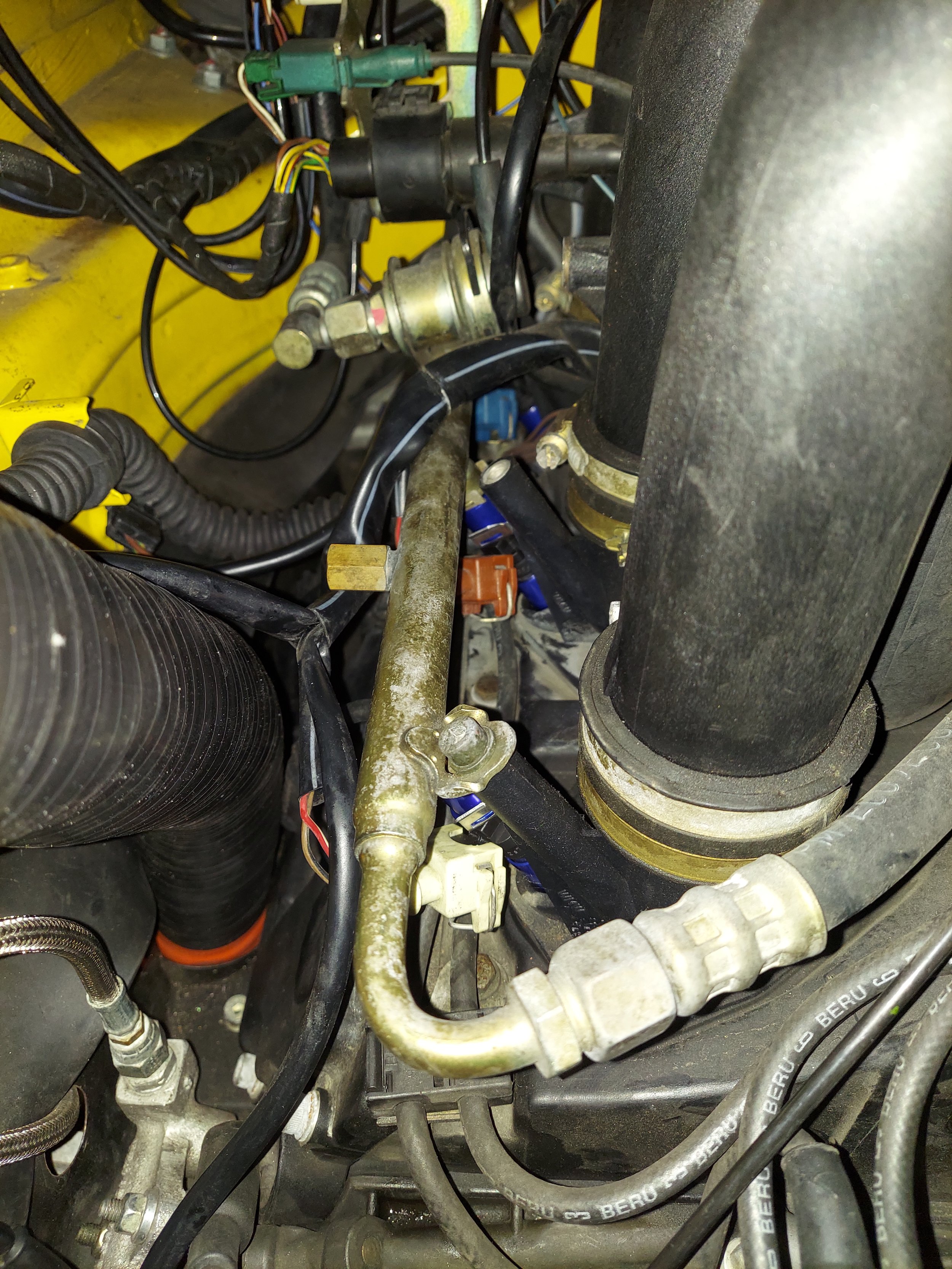
Remove the evap vac hose cap to install the new supplied vac hose to the new map sensor
-
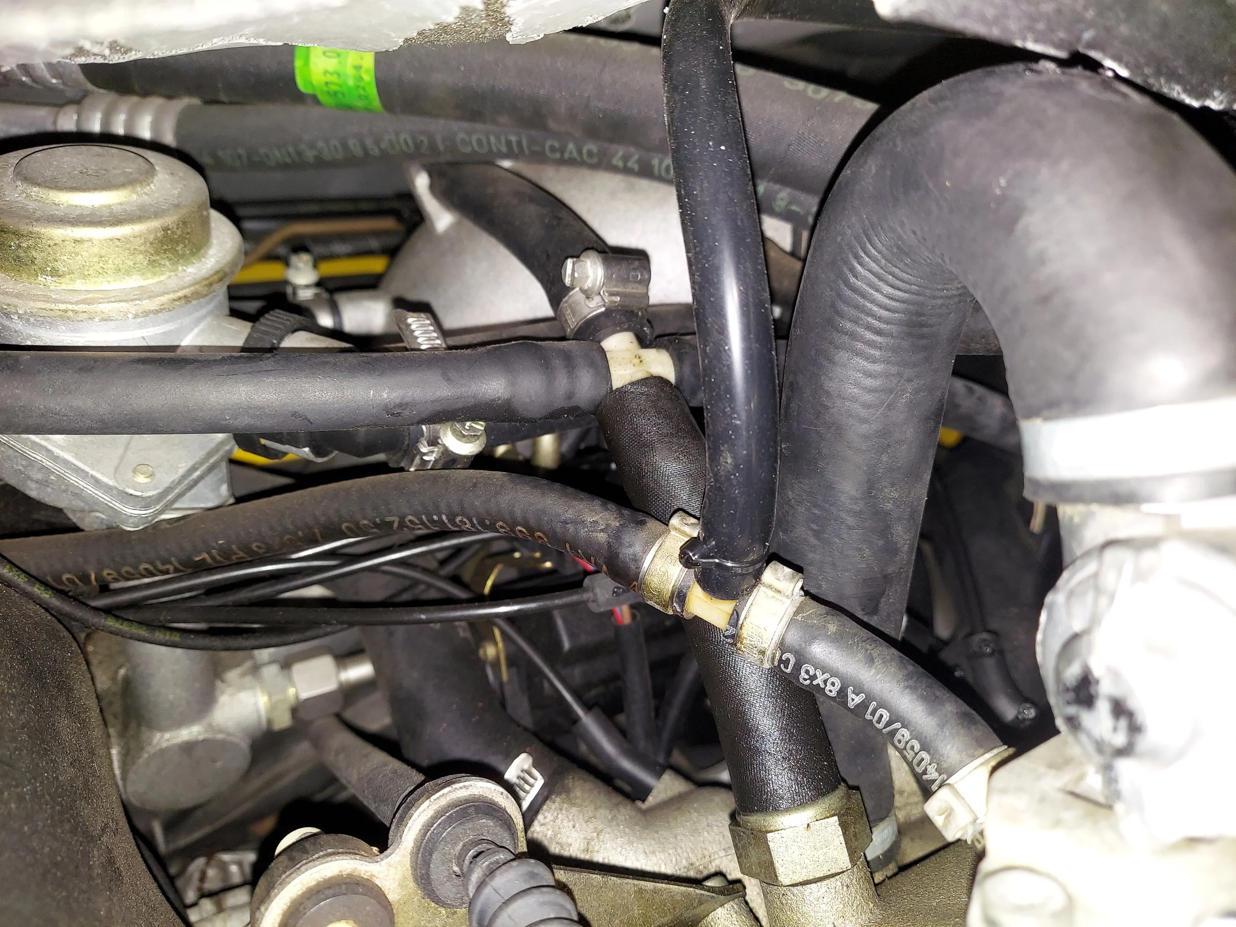
Install the new vac hose and zip tie on fitting to secure
-
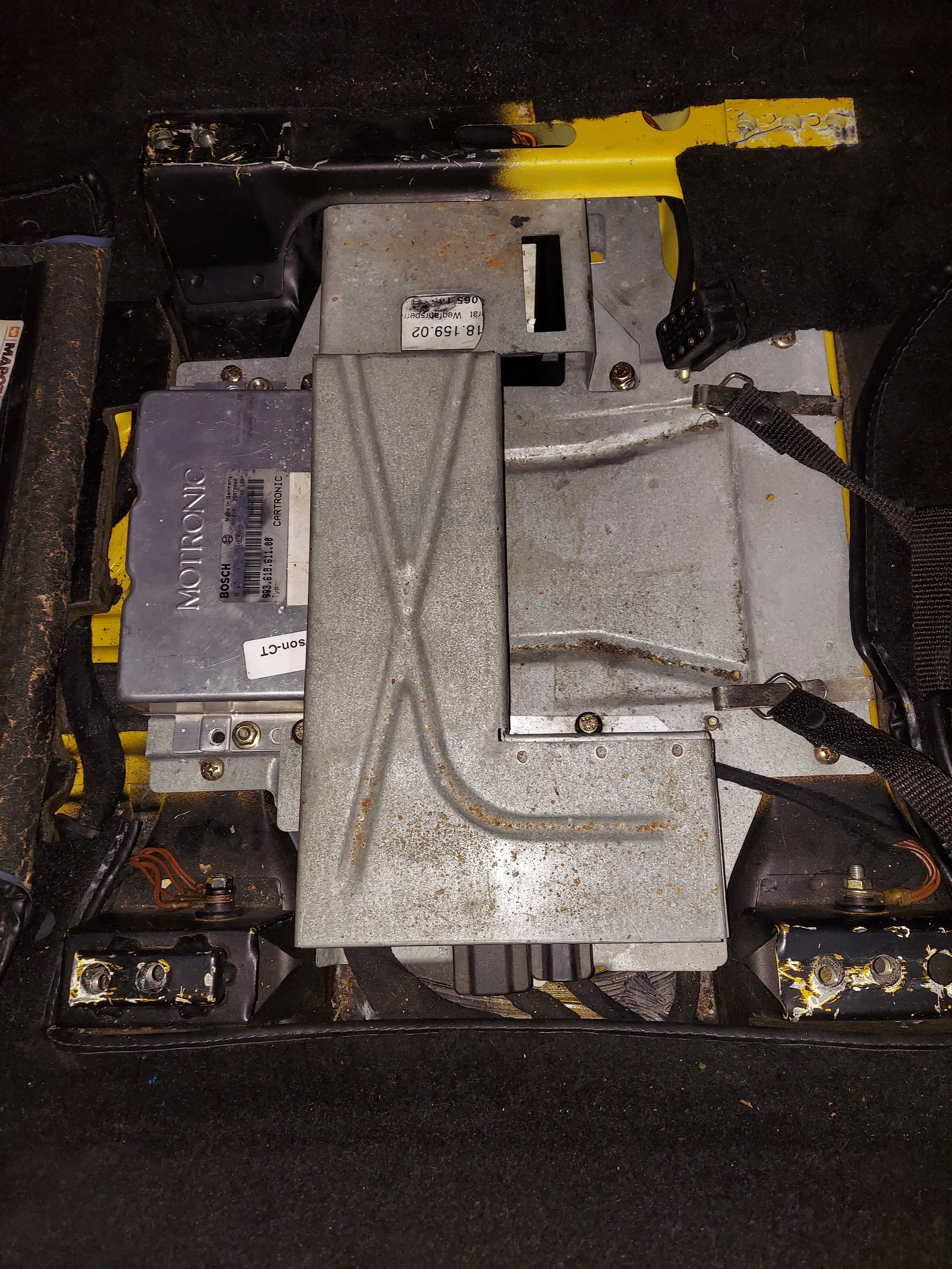
You’ll need to remove the drivers seat to access the DME. There are four allen bolts that hold the seat down. Make sure you disconnect any wiring also.
Next remove the metal protective cover for the DME. This will not be reinstalled
-
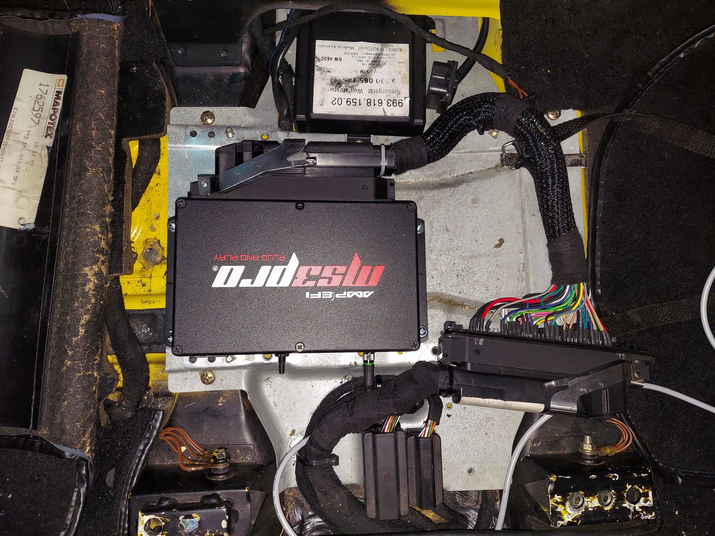
Unbolt the DME and disconnect. Plug in the jumper harness to the new standalone ecu the mark out and mount the ecu with the zip screws supplied.
Plug the jumper harness into the chassis harness. Install the data cable into the ecu and zip tie the harnesses to secure them
-
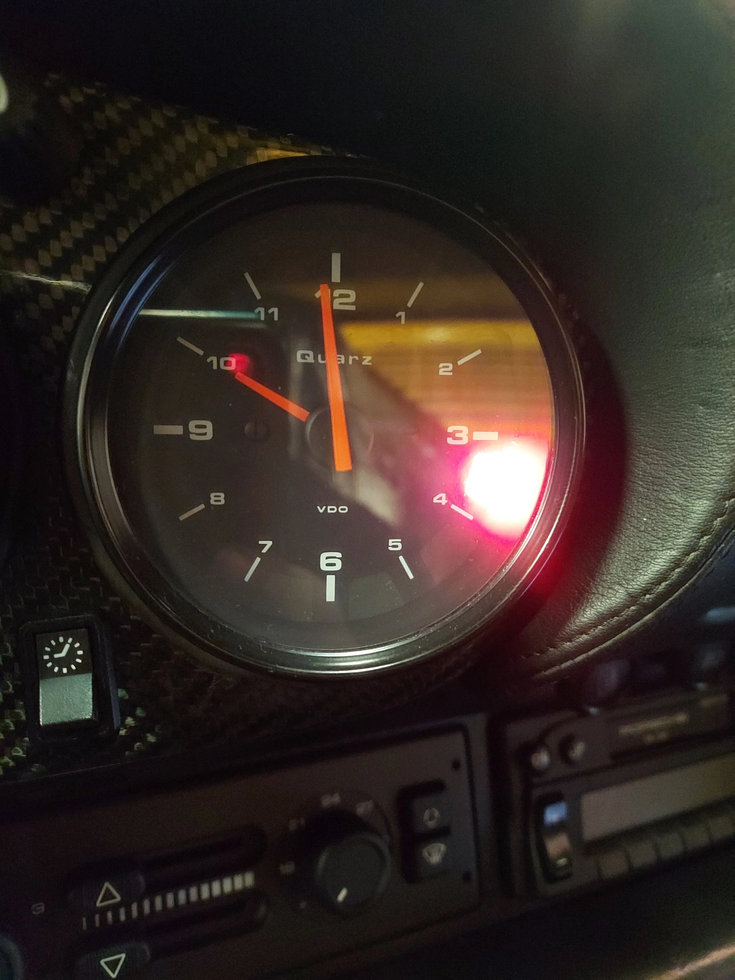
On cars with the antitheft immobilizer you can remove the light bulb for the remote. The clock is push fit into the rubber grommet. Lube may be necessary to aid removal
-
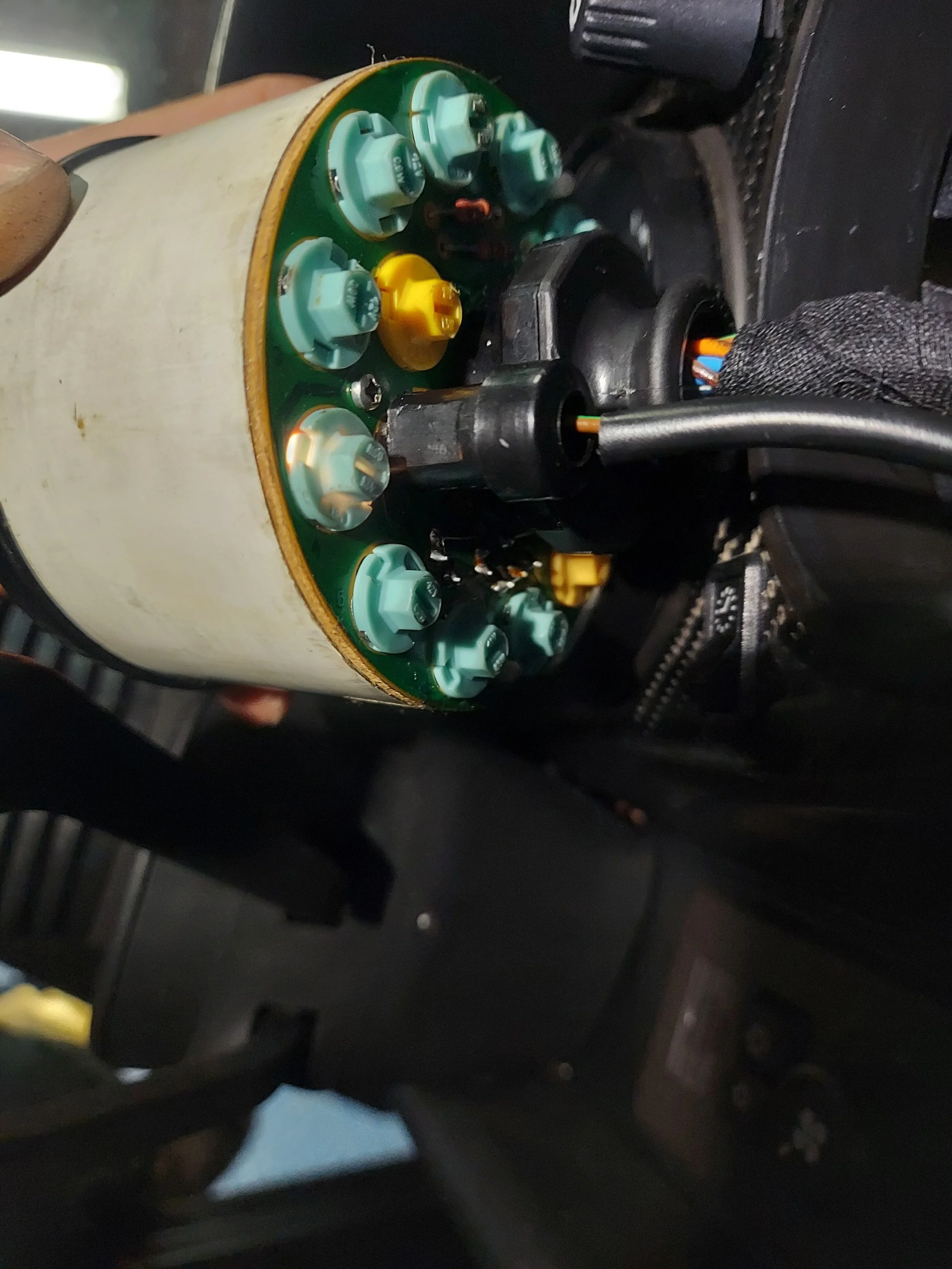
The bulb lit in above pic is to be removed for the antitheft remote
-
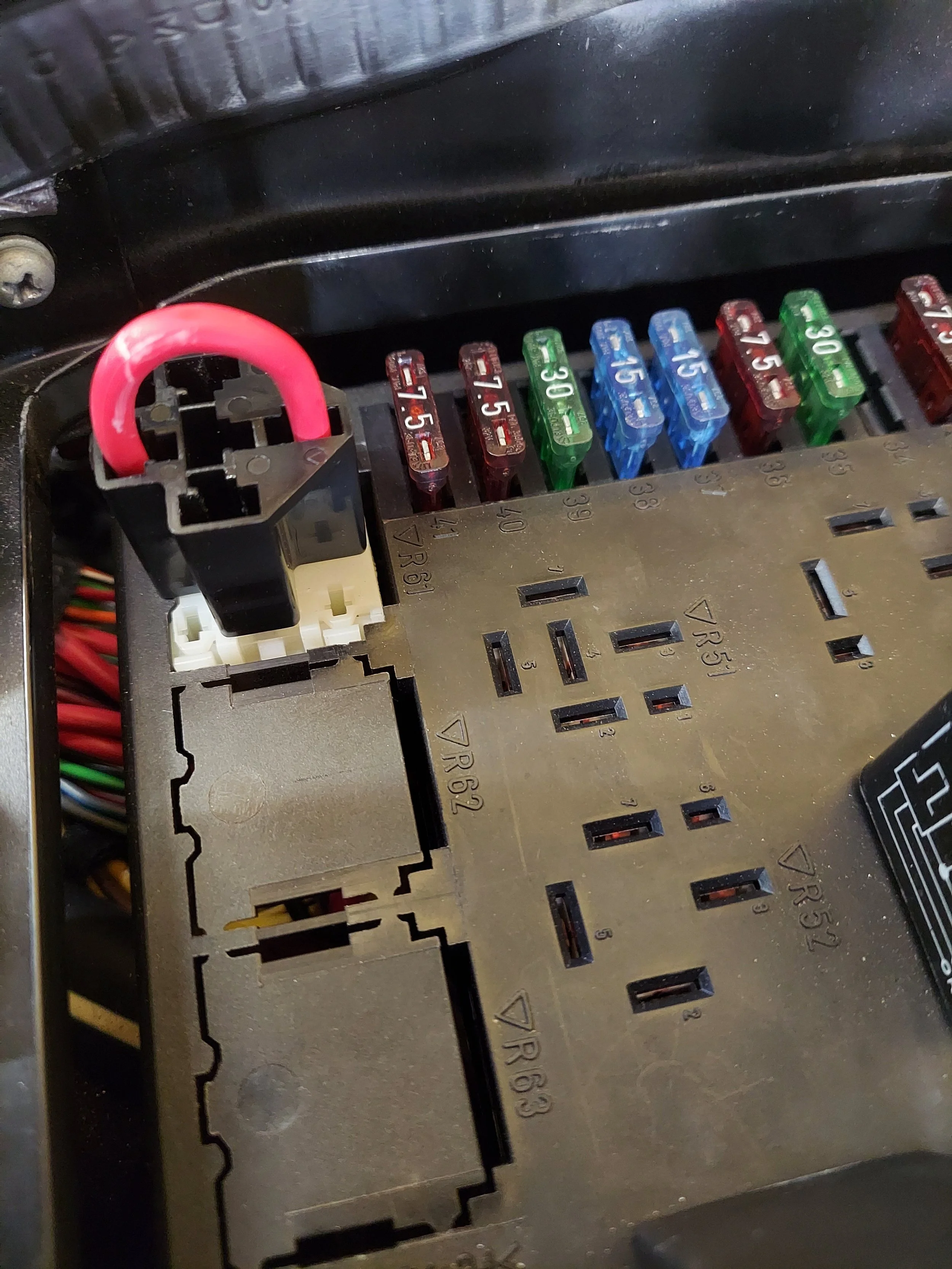
On antitheft immobilizer cars, go into the fuse panel and replace the starter antitheft relay with the supplier jumper. The relay is the gray relay in the upper left corner of the fuse panel
-
Accessory pin out on back of ecu. Pay attention to the connector orientation
-
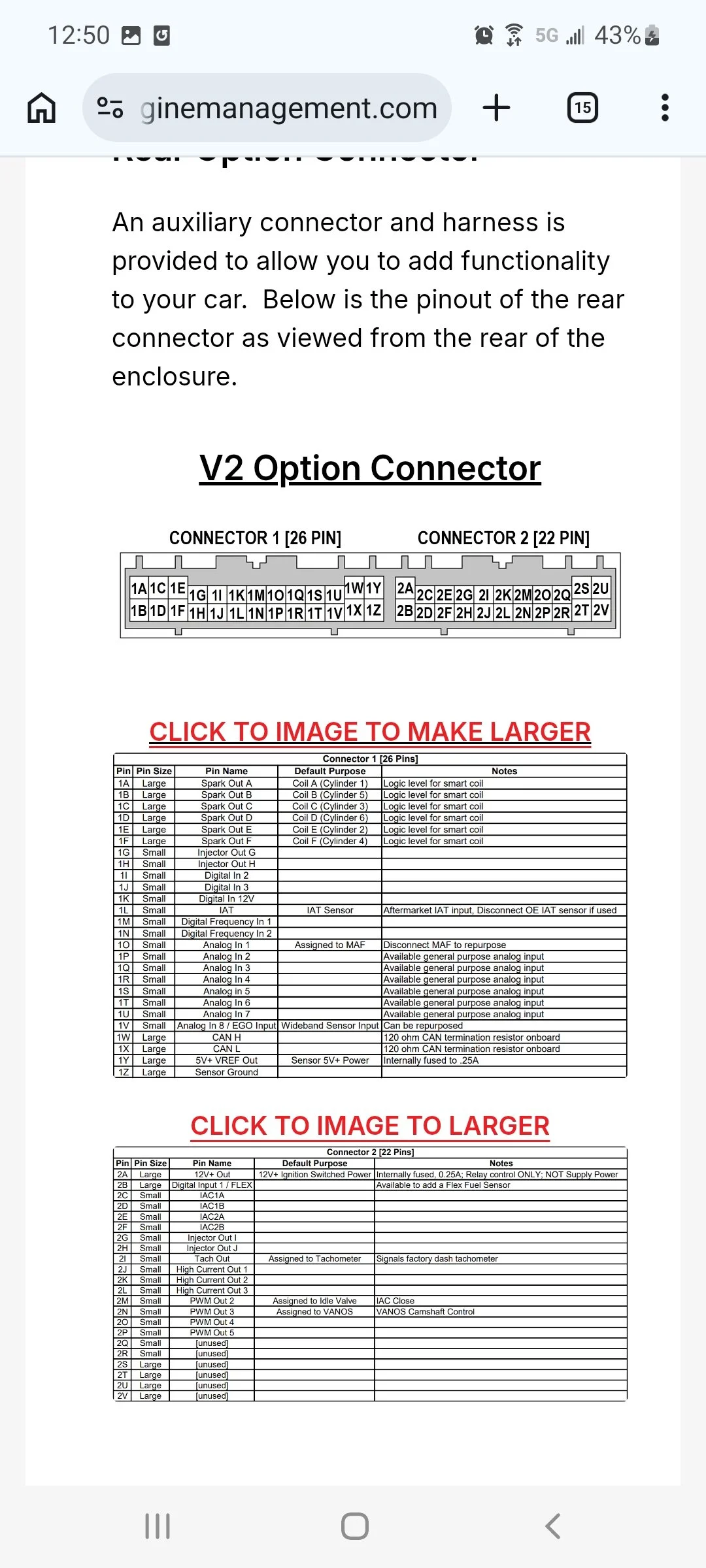
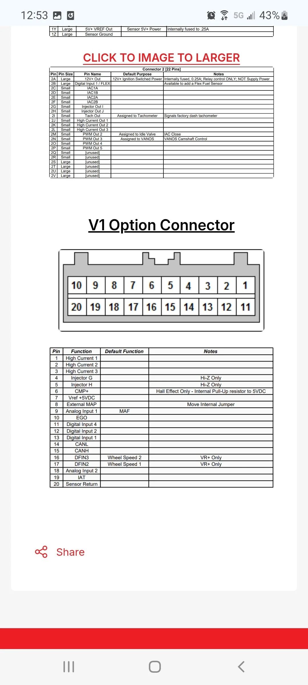
Version 2 connector
-

Version 2 connector pin out
-
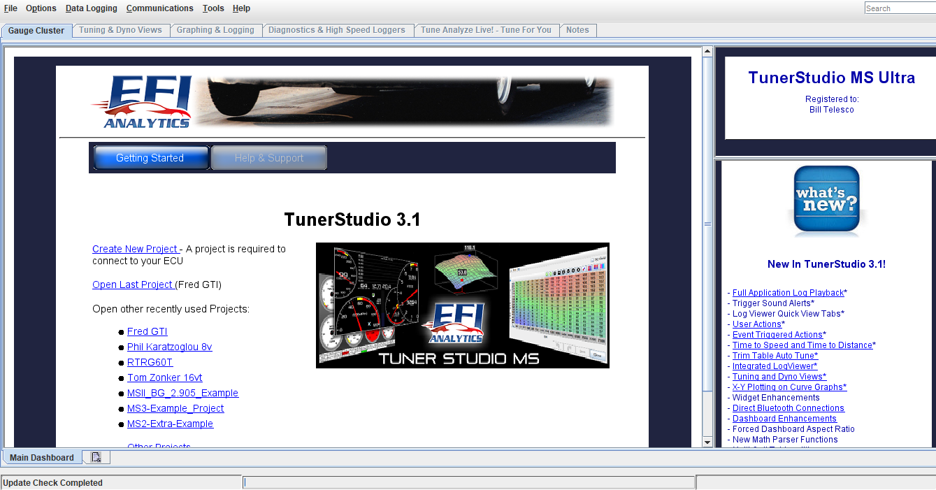
Open the tuner studio software. link http://www.tunerstudio.com/index.php/downloads
This is the main page. Click create new project
-
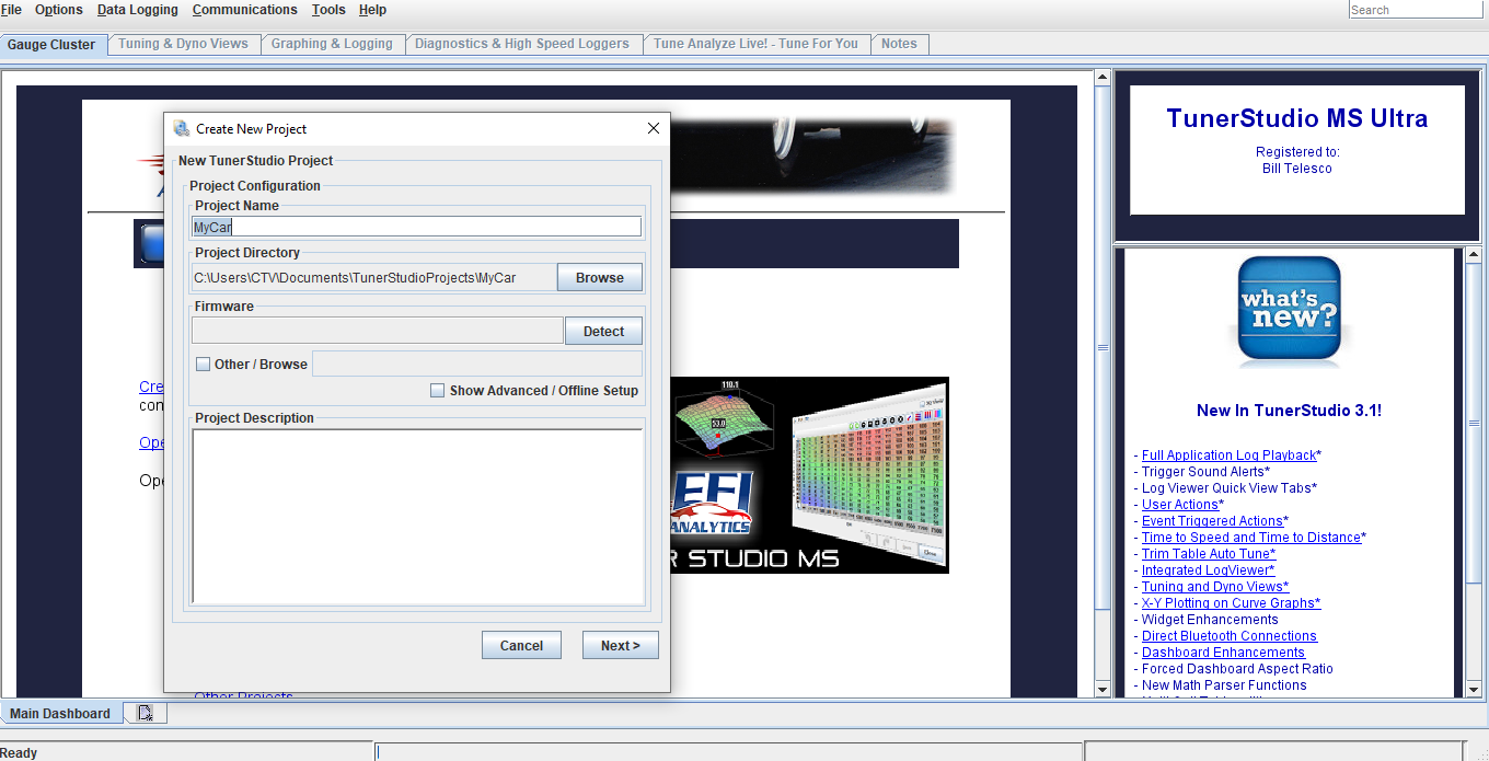
Add project name. Click detect, this will search for the ecu. Key must be in on position to power up ecu and the data cable hooked to the ecu with serial to usb adapter hooked up to your laptop/tuning computer. If it does not detect, you will probably need to download the driver file for the usb adapter or change the communication baud rate (it is usually a driver file missing). I have made sure to bench tested all the cables, sensors, and harness in your kit directly with your ecu before shipping.
-
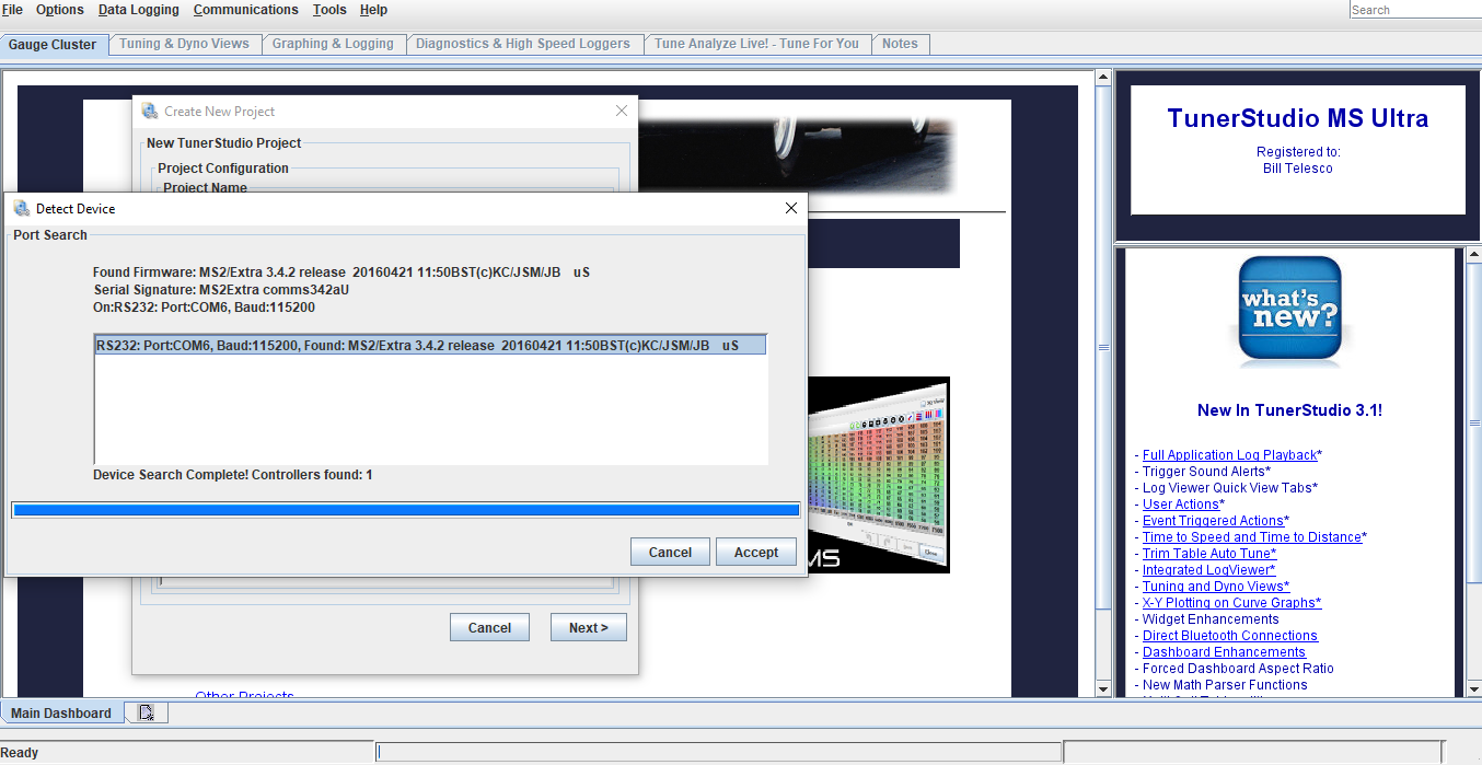
Once ecu has been detected, click accept, then click next
-
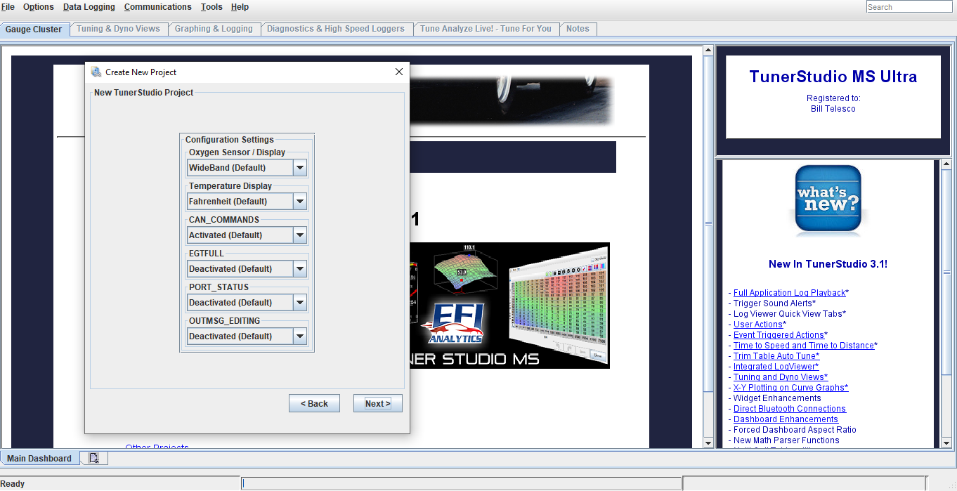
Next screen is Configuration settings. These do not need to be touch, the default settings are good. Click next
-
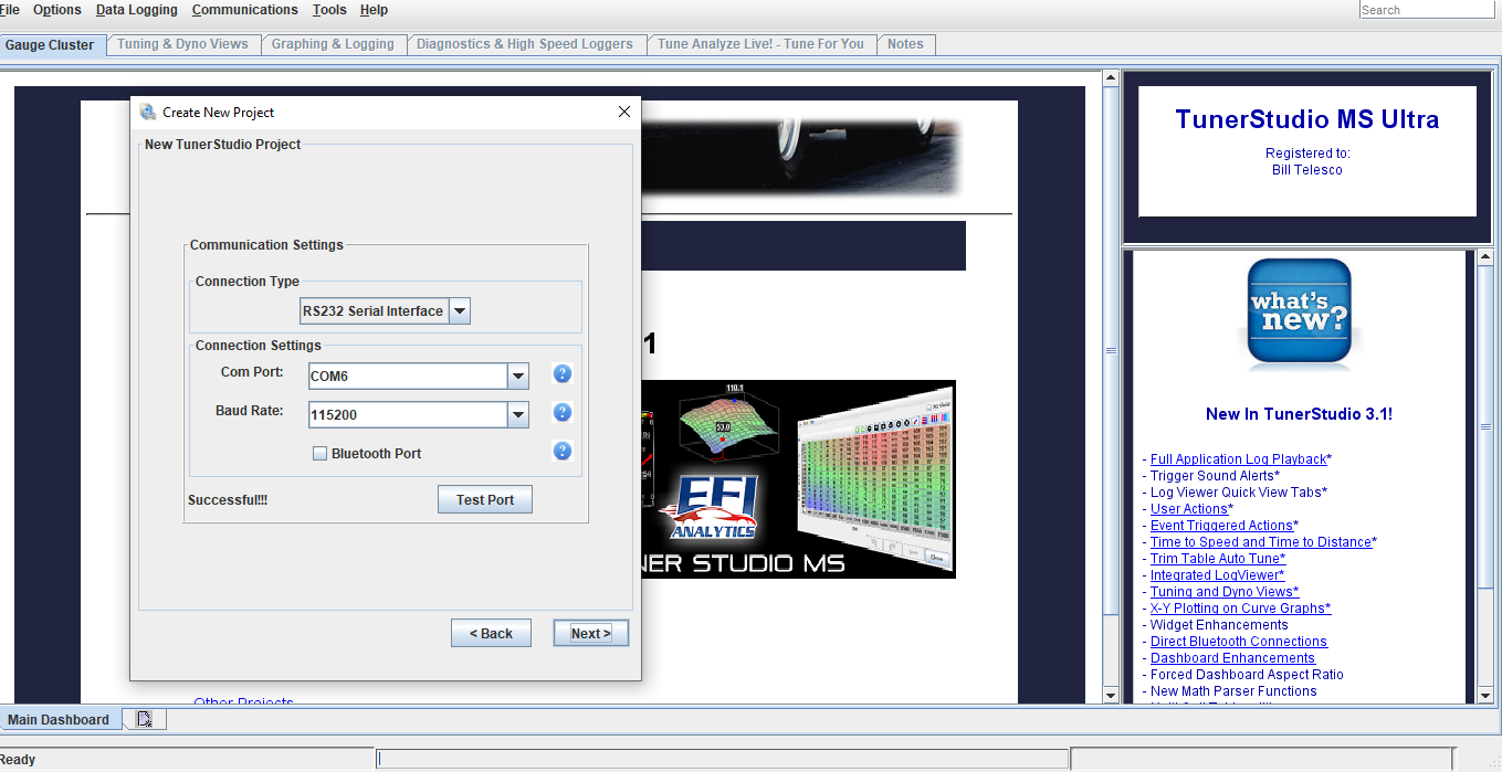
Next screen is Communication settings. Click test port, it should come back successful. Click next
-
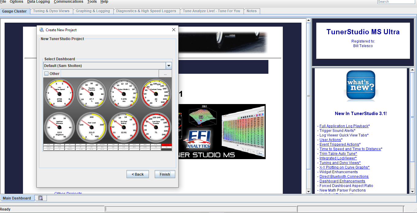
Next screen is dashboard. This is the gauge display you will see once the ecu has been connected to tuner studio. You can leave it on default, but I recommend downloading the dashboard display I have emailed over with the base file copy and installing that. To do that check other, then click the 3 dots in the right corner to browse for the file download.
Note: If using the lite free version this option will not work
-
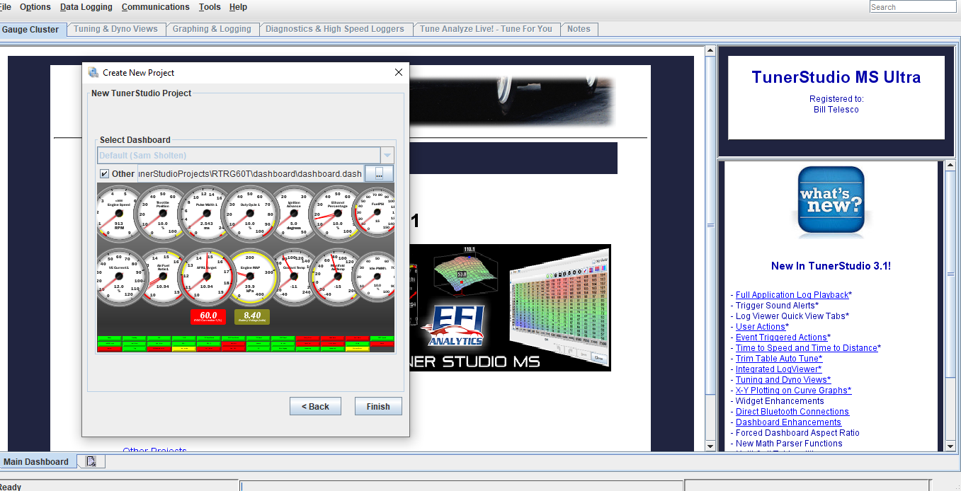
Once new dashboard has been downloaded, you’ll see there’s a lot more gauges for viewing data added. Click finish and that will conclude the initial setup
-
You will now be able to see your dashboard gauges. If you have chosen to download the custom dash display I sent over, there are a lot more gauge with the important data.
-
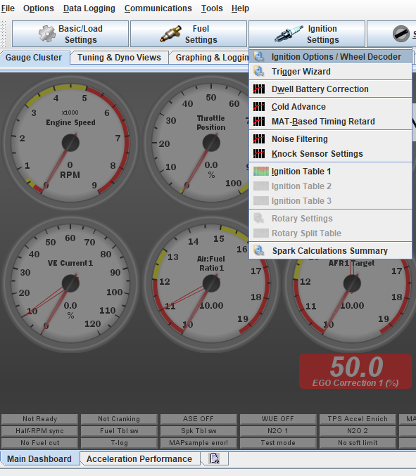
The next step is recommended, ignition timing must be checked/set with a timing light. To do this we are going to go into the the software and lock the ignition at a set degree. On the main dashboard click the Ignition Settings tab, then ignition options
-
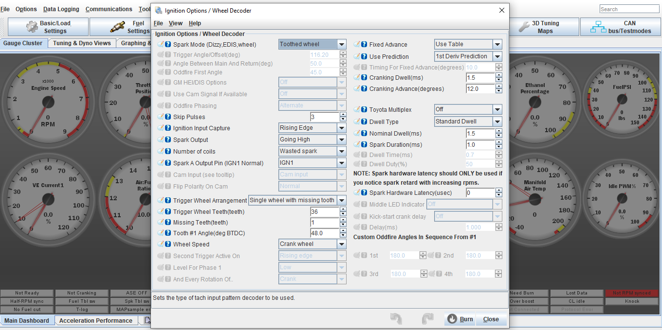
In ignition settings, under fixed advance, switch from user table to fixed timing. Now check Timing for fixed advance (degrees), it should already be set at 10, if not type in 10 for 10 degrees, Hit burn. You should hear the car idle down some since timing has now been retarded. You can now verify that the Tooth #1 angle is set correctly by checking timing with a timing light. The timing light and marks should read/line up 10*, if not adjust the Tooth #1 angle setting until the timing marks line up on the flywheel/bellhousing. Once timing is set and verified, go back into ignition settings and switch from fixed timing back to user table, hit burn.
AGAIN DO NOT SKIP THIS STEP!!!!!
-
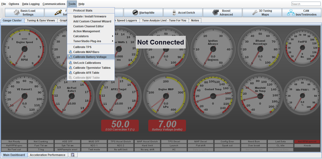
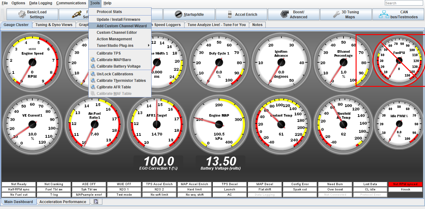
Next is to check the battery voltage calibration. This will directly affect the fuel mixture as a whole.
Click tools, Calibrate Battery Voltage
-
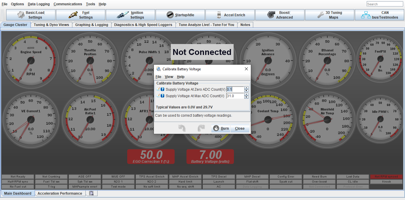
Using a voltmeter, check at the battery what voltage is and compare to the battery voltage reading on the ecu dash display.
DO NOT use the dash/center console gauge as a reading.
Adjust the Supply Voltage Max up/down if needed. The ecu battery voltage will be always fluctuating, so just get it close to the voltmeter reading
-
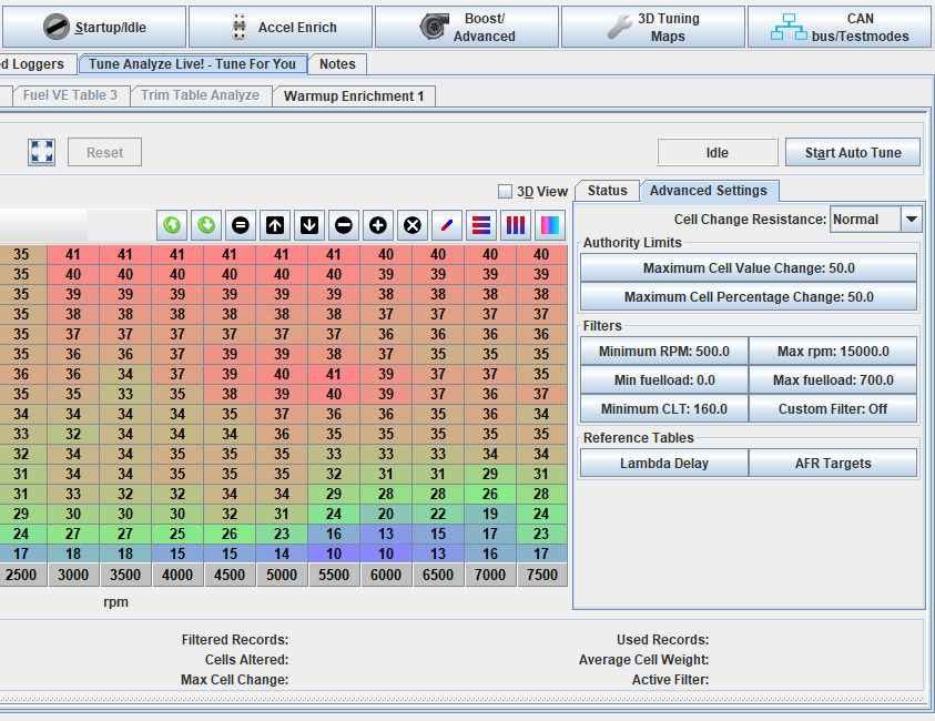
Now that timing is set and battery cal checked, the car should be warmed up and it’s time to start dialing in the fuel with the autotune feature. On the main dashboard click Tune Analyzer Live, then advanced settings. The autotune won’t work unless the coolant temp is above the minimum clt temp. This should be set to 140-160*. If your engine is above those temps (which can be checked on the main dashboard) click start autotune. You will see the tracer moving and correcting cells in the fuel map. Click on the status bar, you will see in cell weighting the chart changing color, once you see dark green in those areas, fuel should be dialed in to the settings on the afr chart (I have preset the afr settings in the fuel settings)
-
Once idle afr is dialed in its time to start driving the car and letting the autotune do its magic. Drive the car around, IN A NORMAL CONTROLED MANNER, around town and on the highway. You will see colors start popping up in the cell weighting area. Once the cell weighting is dark green in those areas on the you can start doing full throttle pulls. Note that the tracer will only hit certain load areas, this is normal. Keep an eye on your o2 gauge to see where afr is at.
AFR targets: Idle 13.6 on most apps, Cruising and around town 13.8-14.5, full throttle NA engines 12.8-13.3.
Full throttle on boosted engines 11.2-11.8.
Start on the lowest boost setting possible and work your way up.
On boosted apps don’t go for broke and just start hammering it full throttle, do easy progressive pulls so the ecu can correct the fuel. If you see lean mixture, get out of the throttle, wait a few seconds then do another pull. On turbo apps pay attention to your intake temps when doing pulls. Try not to go over 120*f. When your finished tuning click apply/burn/save on ecu, then save on ecu. This will burn the autotune changes to the ecu. Turn the autotune off when done.
Save a copy of config file as a backup as well under file, save config. Files and logs will be stored in Documents under Tuner Studio.
If you are uncertain at any time or uncomfortable with tuning, contact us and we will help get you sorted.
DONT BE STUPID, you can hurt your engine very easy with lean afr, Ping/Knock and full throttle driving like speed racer, especially under boost.
-
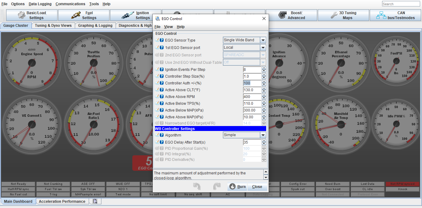
Once your warm engine tune has been complete we can turn the EGO/O2 correction control percentage down. It has been set to 100% in order to make tuning easier.
Go into Fuel Settings, Ego Control, and turn Controller Authority down to 20%
Click Burn
-

If your setup is turbo and using the electronic boost control, we can setup the safeties and boost control.
Click Boost/Advance tab, Boost Control Settings
-
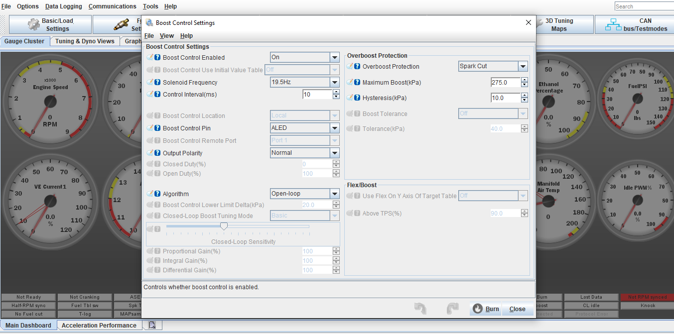
Copy the settings on this screen. Work with the open loop setting first until you understand how the boost control works. From there you can setup a closed loop map if wanted.
For Over boost Protection, set this about 5-8lbs higher than the max boost you would like to run. I will usually pre set this based on our consultation about your setup
-
Next is to setup the open loop table. Click the Boost/Advance tab, Boost Control Duty Table
-
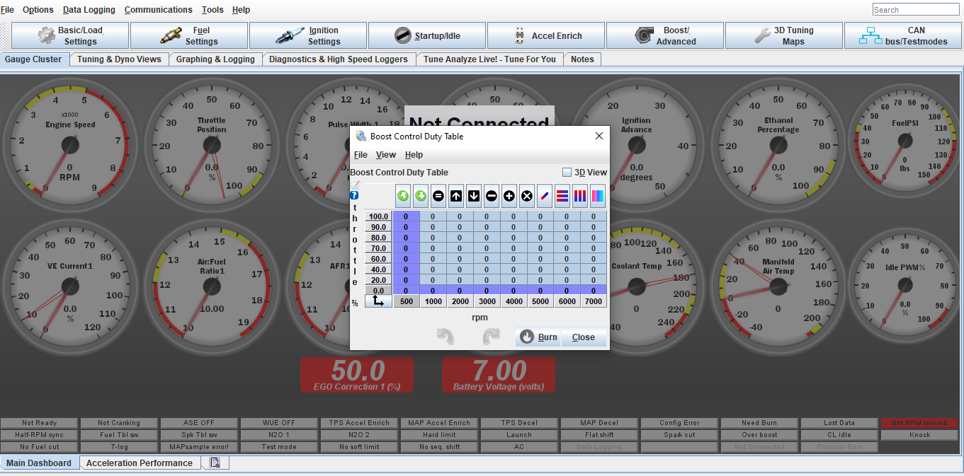
This table will be set at your discretion. This is direct duty cycle% control on the solenoid. Max duty cycle should not go over 85%.
It is best to start off with the way the table is highlighted and increase the cells in 5-10% changes until you figure out how much the % vs boost is. From there you can build a curve and ramp boost up/down vs desired power/boost level or to act as traction control for wheel spin. This is where the data logging is very useful
-
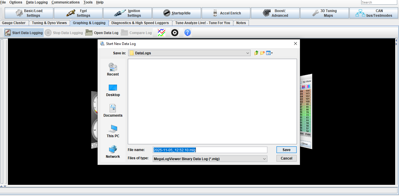
To Data log click Graphing and Logging tab, Start Data logging, Click save on the pop up screen, Click Stop Data logging when done.
The log will stay open on the screen.
To open an old data log click open data log and select your file
-
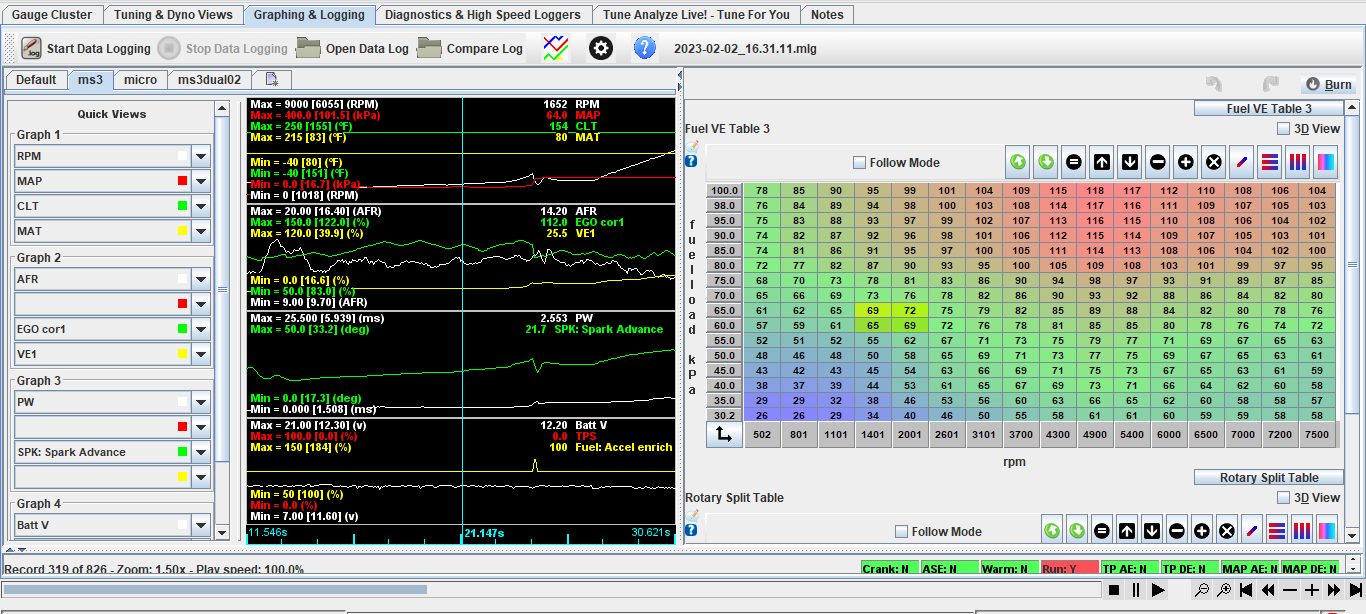
Select the data you would like to view in the log. You can save your data view list by clicking the quick view tab window in the corner. This saves time from having to setup the list every time you view a log